

- Home >
- Products >
- Technical Highlight >
- Vol.1: Pipeline Girth Welding:Kobe Steel's up-to-date welding consumables meet diverse requirements >
Technical Highlight Vol.1

1 Preface
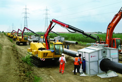
Because growing populations in developing countries create ever more demand for energy, investments in mining, transportation and storage of energy resources and relevant equipment are expected to increase. Used for stable and continuous transport of crude oil and natural gas, pipelines, in small and large sizes, play a key role in energy infrastructure worldwide.
There are two major types of pipeline: on-shore, pictured in Figure 1, and subsea pipelines. Two methods of installing subsea pipelines are used. One is called the S-Lay or J-Lay method, in which pipes are girth-welded on board a ship and then lowered to the seabed. In contrast, the spooled pipe method has the pipes girth-welded into one long pipe (a few km in length). It is wound or spooled onto a bobbin and carried to a ship for installation under the seabed.
SMAW, GTAW, GMAW and SAW are the processes most often applied for welding the pipes used in pipelines. However, SAW tends to be limited to welding the longitudinal pipe seams whereas the other processes are used for circumferential girth welding. This article focuses on the up-to-date welding consumables for onsite girth welding.
2 Girth welding and requirements for welding consumables
The specifications required of pipelines vary, depending on materials (strength requirements), sizes (pipe diameter), construction site conditions (temperature, on-shore or seabed), and service condition (pressure). Most countries also have their own particular regulations and requirements that will influence a pipeline’s specifications – and raise issues when pipelines cross borders.
Cellulose type covered electrodes, used in vertical downward position (from 12 to 6 o’clock), have been preferred for girth welding from the start of pipeline history because of their fast welding speed. Their use, however, is limited to warm areas due to their low crack resistance and that a certain degree of welding skill is necessary. More recently they are being replaced by self-shielded flux cored wires (SS-FCWs). Nevertheless, both of these welding consumables still account for 70 to 80 % of total girth welding.
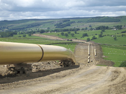
Figure 1: Onshore pipeline
Photo courtesy of Pipeline Service S.r.I.,
Manufacturer of the Proteus FAP.
Because construction, transportation and installation of pipelines require significant investments of time and money, demand is high for the most efficient girth welding processes. As seen in Figure 2, the application of exclusive girth welding equipment with automatic GMAW has gradually been expanding and replacing covered electrodes and SS-FCWs. The use of solid wires as well as metal type FCWs that enable vertical downward welding is also rising.
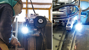
Figure 2: MAG welding by special girth welding machine.
Photo courtesy of Pipeline Service S.r.I., Manufacturer of the Proteus FAP.
Because pipe constructed with the spooled pipe method is wound on a bobbin after welding, mechanical properties like ductility and strength as well as the inspection methods of the weld metal have to be carefully considered when designing the weld metal and setting-up the welding procedures. For example, vertical downward welding by conventional GMAW with solid wires often suffers from lack-of-penetration that can increase the need for future repairs. Therefore, all-positional FCWs that enable vertical upward welding with deep and stable penetration are preferable. Furthermore, because higher strength pipe like API 5L X80 grade is being considered for actual pipeline projects, FCWs with the quality and efficiency suitable for higher strength pipes are now a must for development.
The grades of carbon steel that are suited to pipeline pipes range from API 5L X52 to X100, as shown in Tables 1 and 2. Clad pipes (Ni base) are also available from the view point of corrosion resistance.
3 Carbon steel welding consumables suitable for girth welding
Kobe Steel has been marketing welding consumables for girth welding for decades. Table 1 shows the typical covered electrodes for girth welding while Table 2 shows the TIG and MAG wires for particular grades of steel.
4 Up-to-date welding consumables for girth welding
4.1.  LB-52NSU
When pipe root pass welding must be conducted from outside rather than inside in order to form the back bead inside the pipe, GTAW or SMAW are generally favored. Kobe Steel has long marketed FAMILIARC™ LB-52U as well as FAMILIARC™ LB-62U for this purpose, and they still serve as Kobe’s most reliable, “one and only” products worldwide.
In addition to meeting the always-changing and diverse specifications of pipelines, TRUSTARC™ LB-52NSU has been developed specifically for root pass welding of pipes for low temperature service. It is a covered, low hydrogen type electrode equivalent to AWS A5.5 E7016-G. It offers superb notch toughness at -60°C and very low diffusible hydrogen content of about 3.0ml/100g. The chemistries, mechanical properties of all weld metal and diffusible hydrogen content of TRUSTARC™ LB-52NSU are shown in Tables 3, 4 and 5 respectively.
| API 5L pipe grade |
Welding pass |
Low hydrogen type | High cellulose type |
|
|---|---|---|---|---|
| Vertical upward position |
Vertical downward position |
|||
| X42-X52 | Root | LB-52U LB-52NSU |
LB-78VS | KOBE-6010 |
| Hot | LB-52-18 LB-52NS |
|||
| Filler & Cap | ||||
| X56-X60 | Root | LB-52U LB-52NSU |
KOBE-6010 KOBE-7010S |
|
| Hot | LB-52-18 LB-52NS |
KOBE-7010S | ||
| Filler & Cap | ||||
| X65 | Root | LB-52U | LB-88VS | KOBE-7010S KOBE-8010S |
| Hot | LB-62 LB-62D |
|||
| Filler & Cap | KOBE-8010S | |||
| X70 | Root | LB-62U | KOBE-7010S KOBE-8010S |
|
| Hot | LB-62 LB-62D |
|||
| Filler & Cap | KOBE-8010S | |||
| X80 | Root | LB-62U | LB-98VS LB-108VS |
—— |
| Hot | LB-65D LB-106 |
|||
| Filler & Cap | ||||
| X100 | Root | —— | LB-118VS | —— |
| Hot | LB-80L LB-116 |
|||
| Filler & Cap | ||||
| API 5L pipe grade |
Welding pass |
Temperature (°C) | ||
|---|---|---|---|---|
| -20 | -40 | -60 | ||
| X42-X56 | Root & Hot | TG-S50 MX-100T |
TG-S1N MX-A55T |
|
| Filler & Cap | DW-A50 DW-A50SR |
DW-A55E DW-A55ESR |
DW-A55L DW-A55LSR DW-A81Ni1 |
|
| X60 | Root & Hot | TG-S62 | TG-S60A | |
| Filler & Cap | DW-A55E DW-A55ESR |
DW-A55L DW-A55LSR DW-A81Ni1 |
||
| X65 | Root & Hot | TG-S62 | TG-S60A | |
| Filler & Cap | DW-A55E DW-A55ESR |
DW-A55L DW-A55LSR DW-A81Ni1 |
||
| X70 | Root & Hot | TG-S62 | TG-S60A | |
| Filler & Cap | DW-A70L | DW-A55L DW-A81Ni1 |
||
| X80 | Root & Hot | TG-S80AM | ||
| Filler & Cap | DW-A70L | —— | ||
| X100 | Root & Hot | TG-S80AM | ||
| Filler & Cap | DW-A80L | —— | —— | |
| C | Si | Mn | P | S | Ni | Ti | B |
|---|---|---|---|---|---|---|---|
| 0.06 | 0.62 | 1.25 | 0.016 | 0.004 | 0.50 | 0.014 | 0.0027 |
| Tensile properties | Notch toughness | ||||||
|---|---|---|---|---|---|---|---|
| 0.2% PS (MPa) |
TS (MPa) |
EI (%) |
RA (%) |
Absorbed energy:J (Brittle fracture: %) |
FATT (°C) |
||
| -80°C | -60°C | -40°C | |||||
| 511 | 598 | 32 | 78 | 43(60) 55(60) 41(60) Av.46(60) |
44(55) 72(55) 58(52) Av.58(54) |
70(50) 137(35) 144(35) Av.117(40) |
-53 |
| Electrode dia (mm) | 1 | 2 | 3 | 4 | Ave. |
|---|---|---|---|---|---|
| 3.2 | 2.8 | 3.3 | 3.5 | 3.0 | 3.2 |
Note: Tested method: According to AWS A4.3.(Gas chromatography)
Welding current: 120 A (DCEP)
Welding atmosphere: 21°C x RH10%
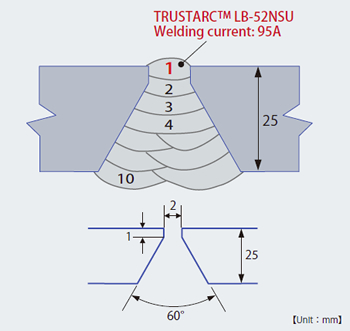
Figure 3: Groove shape and pass sequence of butt joint
welding with TRUSTARCTM LB-52NSU(root pass only)
and TRUSTARCTM LB-52NS
In welding a butt joint on a 25 mm thick plate, 3.2 mm dia. TRUSTARC™ LB-52NSU was used for the root pass with DC 95 amp, and 3.2 mm dia. TRUSTARC™ LB-52NS was used for the second pass onwards with DC 110 amp in the vertical upward position. The preheating and interpass temperatures were kept between 115 and 135°C. Figure 3 shows the groove shape and the pass sequence and Figure 4, the macrostructure of the weld metal. The chemistries and the tensile properties are shown in Tables 6 and 7, respectively and the notch toughness properties and the transition curve of the butt joint weld metal are shown in Table 8 and Figure 5, respectively. (Note: both TRUSTARC™ LB-52NSU and TRUSTARC™ LB-52NS are specified as AWS A5.5 E7016-G).
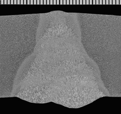
Figure 4: Macrostructure of butt joint weld
metal
| Location | C | Si | Mn | P | S | Ni | Ti | B |
|---|---|---|---|---|---|---|---|---|
| Face | 0.07 | 0.31 | 1.40 | 0.008 | 0.003 | 0.50 | 0.013 | 0.0022 |
| Reverse | 0.08 | 0.30 | 1.36 | 0.009 | 0.003 | 0.43 | 0.014 | 0.0023 |
| Location | Tensile properties | |||
|---|---|---|---|---|
| Center | 0.2%PS (MPa) |
TS (MPa) |
El (%) |
RA (%) |
| 506 | 577 | 25 | 81 | |
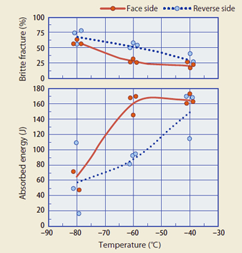
Figure 5: Transition curve of butt joint weld metal
| Location | Notch toughness | |||
|---|---|---|---|---|
| Absorbed energy:J (Brittle fracture: %) |
FATT (°C) |
|||
| -80°C | -60°C | -40°C | ||
| Face side | 47(56) 73(64) 71(55) Av. 64(58) |
169(26) 145(30) 167(26) Av. 160(27) |
162(22) 172(16) 160(26) Av. 165(21) |
-75 |
| Reverse side | 17(79) 108(56) 49(73) Av. 58(69) |
93(53) 92(56) 82(50) Av. 89(53) |
167(26) 114(40) 169(26) Av. 150(31) |
-58 |
4.2. DW-A70L
TRUSTARC™ DW-A70L was developed by Kobe Steel in order to meet the need of pipeline-constructors for high quality and efficiency in welding high strength pipes. A rutile type FCW for all position welding that was designed exclusively for pipeline girth welding. TRUSTARC™ DW-A70L is well suited for welding high strength pipes and for complying with the NACE MR0175 requirement that specifies total Ni content in the weld metal of not more than 1%. The diffusible hydrogen content of TRUSTARC™ DW-A70L all weld metal is as low as 4ml/100g.
Table 9 shows the classification of TRUSTARC™ DW-A70L and Tables 10, 11 and 12, the chemistries, the mechanical properties and the diffusible hydrogen content of TRUSTARC™ DW-A70L all weld metal, respectively.
| Wire diameter | 1.2 mm dia. | |||
|---|---|---|---|---|
| Shielding gas | 80%Ar-20%CO2 | |||
| Welding position | All position | |||
| Classification | AWS A5.29 E101T1-GM ISO 18276 -A- T 62 5 Mn1NiMo P M 2 H5 |
|||
| C | Si | Mn | P | S | Ni | Mo |
|---|---|---|---|---|---|---|
| 0.05 | 0.36 | 1.90 | 0.008 | 0.011 | 0.97 | 0.46 |
| Tensile properties | Notch toughness | ||||||
|---|---|---|---|---|---|---|---|
| 0.2% PS (MPa) |
TS (MPa) |
EI (%) |
RA (%) |
Absorbed energy:J (Brittle fracture: %) |
FATT (°C) |
||
| -50°C | -40°C | -30°C | |||||
| 663 | 739 | 21 | 63 | 75(23) 76(23) 66(30) Av.72(25) |
88(23) 89(18) 84(18) Av.87(20) |
95( 8 ) 92(13) 92(13) Av.93(11) |
<-50 |
| Wire dia (mm) | 1 | 2 | 3 | 4 | Ave. |
|---|---|---|---|---|---|
| 1.2 | 3.5 | 3.7 | 3.9 | 3.6 | 3.7 |
Note: Tested method: According to AWS A4.3.(Gas chromatography)
Welding current: 200A-24V-300mm/min
Wire stick-out length: 25 mm
Using TRUSTARC™ DW-A70L FCW, API 5L X65 pipe was girth-welded with a CRC Evans M300-C welding machine (as shown in Figure 6), and successful results were obtained. Table 13 shows the tested welding conditions. The macrostructure and the bead appearance are shown in Figures 7 and 8, respectively and the chemistries, in Table 14. The mechanical properties and the transition curve of the weld metal are shown in Table 15 and Figure 9 respectively.
| Base metal | API 5L X65-PSL1 273.1 mm dia.× 21.4 mm wall thickness |
|---|---|
| Welding position | 5G (Pipe is fixed in horizontal position.) |
| Welding equipment | M-300-C External Pipe Welding System (CRC-EVANS) |
| Groove shape | 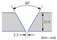 |
| Root & hot passes | TRUSTARCTM TG-S60A (2 layers) Welding parameters: 150 A-10 V-70 mm/min |
| Polarity | DCEP |
| Welding parameters | 200A-23.5V |
| Heat input | 1.7 kJ/mm |
| Pass sequence (FCW) | 8 passes / 5 layers |
| Preheating & Interpass temp. |
100 -130 °C |
| Shielding gas | 80%Ar-20%CO2 , 25 L/min. |
| PWHT | None (As-welded) |
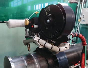
Figure 6: CRC Evans M300-C welding machine
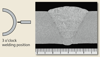
Figure 7: Macrostructure of the weld metal in the 3 o’clock
position
| C | Si | Mn | P | S | Ni | Mo |
|---|---|---|---|---|---|---|
| 0.05 | 0.30 | 1.77 | 0.008 | 0.006 | 0.89 | 0.42 |
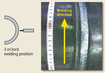
Figure 8: Bead appearance of the weld metal in the 3 o’clock
position
| Tensile properties | Notch toughness | ||||||
|---|---|---|---|---|---|---|---|
| 0.2% PS (MPa) |
TS (MPa) |
EI (%) |
RA (%) |
Absorbed energy:J (Brittle fracture: %) |
FATT (°C) |
||
| -60°C | -50°C | -40°C | |||||
| 627 | 691 | 29 | 66 | 57(37) 63(44) 54(48) Av.58(43) |
63(38) 70(37) 49(45) Av.61(40) |
82(22) 86(23) 82(34) Av.83(26) |
<-60 |
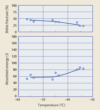
Figure 9: Transition curve of weld metal
As seen in Table 14, Ni content of 0.89 % in the weld metal complies with the NACE requirement. The mechanical properties such as strength (0.2%PS as well as TS) and notch toughness as low as -60°C, are also satisfactory, thanks to the optimization of the alloying elements including minor components in the TRUSTARC™ DW-A70L flux. Finally, the amount and composition of slag in TRUSTARC™ DW-A70L flux is optimum and provides good weldability in all position welding as can be seen in Figures 7 and 8, the macrostructure of the weld metal at 3 o’clock position as well as the bead appearance.
4.3. DW-N625P
Depending on where it is drilled, crude oil or natural gas may sometimes contain substances that can corrode pipes. In such cases, the inner pipe has to be corrosion-resistant, so clad pipes in which the inner surface is overlay-welded are generally used. For girth welding of corrosion-resistant pipes as well as clad steel pipes, Ni-Cr-Mo 625 alloy is normally applied due to its excellent corrosion resistance. Its strength is usually designed to be equal to or better than the pipes being welded.
Until recently, an FCW with good weldability, corrosion resistance as well as appropriate mechanical properties for girth welding was not available in the market. However, Kobe Steel’s newly-developed PREMIARC™ DW-N625P flux cored wire fulfills all the requirements mentioned above. Table 16 shows the classification of PREMIARC™ DW-N625P and Tables 17 and 18, the chemistries and the mechanical properties of PREMIARC™ DW-N625P all weld metal, respectively.
| Wire diameter | 1.2 mm |
|---|---|
| Shielding gas | 75-80%Ar+Bal.%CO2 |
| Welding position | All position |
| Classification | AWS A5.34/A5.34M: ENiCrMo3T1-4 ISO 12153 T Ni 6625 P M21 2 |
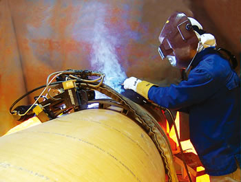
Figure 10: Welding of pipe by PREMIARCTM DW-N625P
and Magnatech machine.
Photograph supplied, courtesy of Magnatech International B.V.
| Elements | C | Si | Mn | P | S | Cu | Ni |
|---|---|---|---|---|---|---|---|
| DW-N625P | 0.031 | 0.21 | 0.02 | 0.007 | 0.004 | 0.01 | 65.2 |
| ENiCrMo3Tx-y | ≤0.10 | ≤0.50 | ≤0.50 | ≤0.02 | ≤0.015 | ≤0.05 | ≥58.0 |
| Elements | Cr | Mo | Ti | Fe | Nb+Ta | Others | |
| DW-N625P | 21.3 | 8.8 | 0.17 | 2.0 | 3.23 | —— | |
| ENiCrMo3Tx-y | 20.0 -23.0 |
8.0 -10.0 |
≤0.40 | ≤5.0 | 3.15-4.15 | ≤5.0 | |
| Welding position |
5G (6 →12 o’clock) |
Pass sequence |
|---|---|---|
| Type of steel |
Carbon steel* | 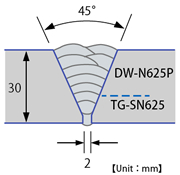 |
| Pipe size | Wall thickness 30 mm Outer diameter 267 mm |
|
| Welding process |
1 -3 passes: GTAW 4-10 passes: FCAW |
|
| Wire | 1-3 passes: TG-SN625 2.4 mm dia. (AWS A5.14 ERNiCrMo3) 4-10 passes: DW-N625P 1.2 mm dia. |
|
| Shielding gas |
1-3 passes: 100%Ar (Back purge: 100%Ar) 4 -10 passes: 80%Ar-20%CO2 (25 l/min) |
|
| Wire stick-out |
4 -10 passes: 15 mm (160A) |
|
| Torch angle |
10°back-hand | |
| Interpass temp. |
150°C max. | |
| * For checking the usability of DW-N625P only | ||
| Tensile properties | Notch toughness | |||||
|---|---|---|---|---|---|---|
| 0.2% PS (MPa) |
TS (MPa) |
EI (%) |
Absorbed energy:J | |||
| -196°C | -100°C | 0°C | ||||
| DW-N625P | 479 | 765 | 45 | Av.70 | Av.78 | Av.84 |
| ENiCrMo3Tx-y | Not required |
≥690 | ≥25 | Not required | ||
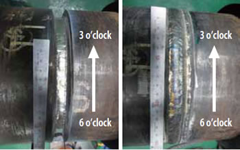
Figure 11: Fourth-pass bead appearance
Figure 12: Cap-pass bead appearance
Figure 10 shows pipe being girth-welded on a Magnatech machine with PREMIARC™ DW-N625P in 5G position. GTAW and FCAW were used to conduct welding according to the welding conditions listed in Table 19. GTAW was used for the root, hot and 3rd passes (3 passes) with PREMIARC™ TG-SN625 rod, and FCAW was used from the 4th pass to the cap pass (10th pass) with PREMIARC™ DW-N625P.
The bead appearances from 6 to 3 o’clock of the 4th pass and the cap pass are shown in Figures 11 and 12, respectively. The macrostructures of 6, 4 and 3 o’clock positions are shown in Figures 13, 14 and 15, respectively. Table 20 shows the impact test results of the 3 o’clock position in the different temperatures down to -196°C.
| Position | Tested temp. (°C) | Absorbed energy (J) |
|---|---|---|
| 3 o’clock | 0 | Av. 96 |
| -30 | Av. 93 | |
| -100 | Av. 87 | |
| -196 | Av. 82 |
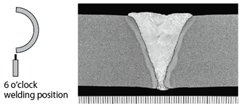
Figure 13: Macrostructure of the weld metal in the 6 o’clock
position
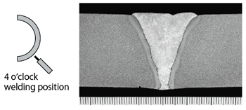
Figure 14: Macrostructure of the weld metal in the 4 o’clock
position
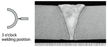
Figure 15: Macrostructure of the weld metal in the 3 o’clock
position
These tests show that girth welding was able to obtain excellent bead appearance at the 6, 4 and 3 o’clock positions which are the most difficult positions in which to achieve defect-free welds.
5 Postscript

Whereas most offshore structures are constructed according to the same specifications and, therefore, will utilize the same welding processes and consumables, pipeline projects are more likely to apply specifications set forth by the particular project owner. For this reason, one project may differ significantly in terms of welding from another. It can be assumed, however, that future pipeline projects will specify ever higher quality requirements.
Demand for more stable and more efficient welding consumables and processes shall not stop and Kobe Steel is always ready to challenge the limits of current technology.
With special thanks, photographs courtesy of:
Pipeline Service S.r.I., Manufacturer of the Proteus FAP Magnatech International B.V.
Products
- Main Products
- Welding Consumables
- Arc welding robots
- Industries - Recommended Materials
- Welding Handbook Quick View
- Product Quick View & Highlights
- For HEAT-RESISTANT STEEL
- For STAINLESS STEEL
- For LOW-TEMPERATURE STEEL
- Product Highlight
- Catalog
- Technical Highlights
- Certification
- SDS ※English Only
- ARCMAN
- Welding Robot
- Software


