

- Home >
- Products >
- Technical Highlight >
- Vol.3: DESIGNING HIGH QUALITY WELDING CONSUMABLES FOR NUCLEAR POWER REACTORS >
Technical Highlight Vol.3
DESIGNING HIGH QUALITY WELDING CONSUMABLES FOR NUCLEAR POWER REACTORS
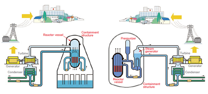
Figure 1: Nuclear power supply systems with a boiling water reactor (left) and with a pressurized water reactor (top).
[Source: Graphical Flip-chart of Nuclear & Energy Related Topics 2010 published by The Federation of Electric Power Companies of Japan].
Nuclear power, increasingly highlighted as a cleaner source of energy than fossil fuels, is seeing a brisk rise in power plant construction, particularly in Asian countries. This article introduces the special steels and welding consumables required for nuclear power plant construction.
Systems of Nuclear Power Generation
| Reactor | Fuel | Moderator | Coolant | Note |
|---|---|---|---|---|
| Light water reactor |
Enriched uranium |
Light water | Light water | ▪ BWR ▪ ABWR ▪ PWR |
| Gas cooled reactor |
Natural or enriched uranium |
Graphite | CO2 | ▪ AGR ▪ Calder Hall AGR |
| Heavy water reactor |
Natural or enriched uranium |
Heavy water | ▪ CO2 ▪ Light water ▪ Heavy water |
|
| Hot gas reactor |
Enriched uranium |
Graphite | Helium | |
| Fast breeder reactor |
Enriched uranium or Plutonium |
None | ▪ Sodium ▪ Na-K alloys |
FBR |
The electricity derived from nuclear power is a form of heat energy, generated by the fission chain reaction of enriched uranium in a reactor vessel, which is transferred to a coolant that produces the steam that rotates a turbine.
There are several types of nuclear reactors, utilizing different moderators and coolants, as shown in Table 1. Figure 1 (left) shows a typical diagram of boiling water reactor (BWR) and Figure 1 (top), a pressurized water reactor (PWR). Both are light water reactors (LWR), the most common types of nuclear reactors.
Nuclear Pressure Vessel Codes
| Testing method | Evaluation criteria |
|---|---|
| Drop weight test | Temperature, 5°C lower than the lowest temperature where both of 2 drop weight test pieces are judged as no-break, is defined as TNDT. |
| Charpy impact test | When all of 3 pieces in a Charpy impact test at the temperature equal to or lower than TNDT + 33°C satisfy the following conditions, TNDT is defined as RTNDT: (1) Absorbed energy is 68 J minimum. (2) Lateral expansion is 0.90 mm minimum. |
While each country defines its own regulations for its nuclear industries, the ASME codes of The American Society of Mechanical Engineering are widely adopted. ASME Sec. III Div. 1 (Nuclear Power Plant Components) and ASME Sec. XI (Rules for Inservice Inspection of Nuclear Power Plant Components); these codes specify in-depth requirements in terms of design, fabrication, test, inspection, and quality assurance. In particular, fracture toughness is one of the key requirements for materials because it governs the resistance to brittle fracture. For example, Table 2 shows the criteria for evaluating Reference Nil Ductility Transition Temperature (RTNDT) obtained through the fracture toughness tests for ferritic materials such as Mn-Mo-Ni steel and weld metal.
Specifications for Steels for Nuclear Reactors
| ASME spec | SA-533 | SA-508 | ||
|---|---|---|---|---|
| Type or grade | Type B | Gr. 2 | Gr. 3 | |
| Class | 1 | 2 | 1 | 1 |
| C (%) | ≤ 0.25 | ≤ 0.25 | ≤ 0.35 | ≤ 0.75 |
| Si | 0.15-0.40 | 0.15-0.40 | 0.15-0.35 | 0.15-0.35 |
| Mn | 1.15-1.50 | 1.15-1.50 | 0.40-0.90 | 0.50-0.90 |
| P | ≤ 0.035 | ≤ 0.035 | ≤ 0.025 | ≤ 0.025 |
| S | ≤ 0.04 | ≤ 0.04 | ≤ 0.025 | ≤ 0.025 |
| Ni | 0.40-0.70 | 0.40-0.70 | ≤ 0.4 | 0.50-1.00 |
| Cr | - | - | ≤ 0.25 | 0.25-0.45 |
| Mo | 0.45-0.60 | 0.45-0.60 | ≤ 0.1 | 0.55-0.70 |
| V | - | - | ≤ 0.05 | ≤ 0.05 |
| 0.2%YS (MPa) |
≥ 345 | ≥ 485 | ≥ 345 | ≥ 345 |
| TS (MPa) | 550-690 | 620-795 | 550-725 | 550-725 |
| El (%) | ≥ 18 | ≥ 16 | ≥ 18 | ≥ 18 |
| RA (%) | - | - | ≥ 38 | ≥ 38 |
| IV at +4.4°C (J) |
- | - | Each ≥ 34 Avg ≥ 41*1 |
Each ≥ 34 Avg ≥ 41*1 |
| Relevant JIS standard |
JIS G 3120 SQV 2 A |
JIS G 3120 SQV 2 B |
JIS G 3204 SFVQ 2 A |
JIS G 3120 SFVQ 1 B |
| *1: The computed average for three specimens. | ||||
Nuclear reactors consist of reactor pressure vessels (RPV); steam generator (SG) and pressurized used only in PWRs; the piping of the primary side cooling; and the containment structure. An RPV operates at high temperatures and high pressures; hence, its components are made of heat resistant steel, namely Mn-Mo-Ni steels as per ASME Sec. II Part A (Ferrous Material Specifications). SA-533 and SA-508 are commonly used for the RPV, as well as the pressurizer and SG in PWRs. Table 3 shows the chemical and mechanical properties and the relevant JIS standards for reference.
For the piping of the primary side cooling system, 304L type stainless steel and Ni-base alloys are mainly used, because of their anti-corrosion properties, high notch toughness and good weldability.
Specifications for Welding Consumables
| Tensile strength class of welding consumable | ||||
|---|---|---|---|---|
| 620 MPa class | 690 MPa class | |||
| Applicable steels (ASME) |
SA-533 Type B Cl.1 SA-508 Gr.2 Cl.1 SA-508 Gr.3 Cl.1 |
SA-533 Type B Cl.2 | ||
| Welding process |
Trade desig. |
AWS class. |
Trade desig. |
AWS class. |
| SMAW | BL-96 | A5.5 E9016-G |
BL-106 | A5.5 E10016-G |
| SAW | MF-27X/ US-56B |
A5.23 F9P4-EG-G |
MF-29AX/ US-63S |
A5.23 F10P2-EG-G |
| PF-200/ US-56B |
A5.23 F9P4-EG-G |
PF-200/ US-63S |
A5.23 F10P2-EG-G |
|
| GTAW | TG-S56 | A5.28 ER80S-G |
TG-S63S | A5.28 ER90S-G |
| Note: MF-27X is a fused flux, while PF-200 is a bonded flux. | ||||
When a nuclear power plant is constructed per ASME Sec. III, the welding consumables must be selected in compliance with ASME Sec. II Part C (Specifications for Welding Rods, Electrodes and Filler Metals), and the welding procedures must be qualified under ASME Sec. IX (Welding and Brazing Qualifications). Because all the welding consumables specified in ASME Sec. II Part C are identical to those in the AWS standard, this article will discuss welding consumables per the AWS standard.
Because safety is of paramount concern in nuclear power generation, the welding consumables must be reliable and have enough strength to withstand at elevated temperatures during operation, low temper embrittlement in case of emergency shutdown, high resistance to neutron irradiation brittleness, and good weldability.
Table 4 shows how welding consumables are matched to Mn-Mo-Ni steels. The welding consumables are divided into two tensile strength classes, 620 and 690 MPa, depending on the applicable steels. The typical chemical and mechanical properties of weld metals by 620 MPa and 690 MPa welding consumables can be seen in Tables 5 and 6, respectively.
| Welding process |
SMAW | SAW | GTAW | |||||
|---|---|---|---|---|---|---|---|---|
| Trade designation |
BL-96 | MF-27X/ US-56B |
PF-200/ US-56B |
TG-S56 | ||||
| Polarity | AC*1 | AC*1 | AC*1 | DCEN | ||||
| C (%) | 0.06 | 0.08 | 0.08 | 0.05 | ||||
| Si | 0.54 | 0.28 | 0.11 | 0.41 | ||||
| Mn | 1.30 | 1.05 | 1.23 | 1.54 | ||||
| P | 0.005 | 0.009 | 0.007 | 0.008 | ||||
| S | 0.004 | 0.004 | 0.003 | 0.006 | ||||
| Cu | 0.02 | 0.08*2 | 0.08*2 | 0.15*2 | ||||
| Ni | 0.37 | 0.87 | 0.83 | 0.66 | ||||
| Cr | 0.02 | 0.06 | 0.02 | 0.03 | ||||
| Mo | 0.53 | 0.50 | 0.43 | 0.52 | ||||
| Co | 0.005 | 0.005 | 0.005 | 0.005 | ||||
| PWHT (°C×hr) |
620× 1 |
600× 16 |
595× 3 |
635× 26 |
590× 3 |
620× 11 |
620× 1 |
650× 15 |
| 0.2%YS (MPa) |
620 | 575 | 528 | 480 | 580 | 490 | 520 | 499 |
| TS (MPa) | 700 | 667 | 618 | 560 | 669 | 580 | 590 | 564 |
| El (%) | 26 | 25 | 33 | 32 | 28 | 30 | 31 | 33 |
| IV at 0°C (J) |
150 | 149 | - | - | - | - | - | - |
| IV at – 10°C (J) |
- | - | - | - | - | - | - | 171 |
| IV at – 12°C (J) |
- | - | 174 | 180 | - | - | 290 | - |
| IV at – 18°C (J) |
- | 89 | - | - | - | - | - | - |
| IV at – 20°C (J) |
- | - | - | - | 189 | 210 | - | - |
| IV at – 40°C (J) |
- | - | 137 | - | 142 | - | - | 204 |
| RTNDT (°C) |
- | –35 | –55 | - | - | - | - | –70 |
| *1 Only for AC. Not recommended for DC. *2 Inclusive of Cu coating. |
||||||||
| Welding process |
SMAW | SAW | GTAW | |||||
|---|---|---|---|---|---|---|---|---|
| Trade designation |
BL-106 | MF-29AX/ US-63S |
PF-200/ US-63S |
TG-S63S | ||||
| Polarity | AC*1 | AC*1 | AC*1 | DCEN | ||||
| C (%) | 0.10 | 0.10 | 0.08 | 0.09 | ||||
| Si | 0.53 | 0.21 | 0.10 | 0.32 | ||||
| Mn | 1.41 | 1.49 | 1.51 | 1.23 | ||||
| P | 0.009 | 0.006 | 0.007 | 0.006 | ||||
| S | 0.005 | 0.005 | 0.004 | 0.006 | ||||
| Cu | 0.02 | 0.07*2 | 0.06*2 | 0.18*2 | ||||
| Ni | 0.76 | 1.35 | 1.31 | 1.58 | ||||
| Cr | 0.04 | 0.17 | 0.14 | 0.04 | ||||
| Mo | 0.50 | 0.51 | 0.47 | 0.40 | ||||
| Co | 0.005 | 0.005 | 0.005 | 0.003 | ||||
| PWHT (°C×hr) |
595× 3 |
613× 15 |
595× 3 |
612× 15 |
590× 3 |
600× 16 |
620× 1 |
635× 16 |
| 0.2%YS (MPa) |
670 | 561 | 640 | 589 | 620 | 552 | 570 | 563 |
| TS (MPa) | 770 | 657 | 740 | 691 | 700 | 641 | 620 | 636 |
| El (%) | 28 | 26 | 28 | 22 | 28 | 28 | 28 | 29 |
| IV at 0°C (J) |
110 | 170 | - | - | - | - | - | - |
| IV at – 10°C (J) |
- | - | - | - | - | - | - | 166 |
| IV at – 12°C (J) |
- | - | 120 | 105 | - | - | - | - |
| IV at – 15°C (J) |
- | - | - | - | - | 235 | - | - |
| IV at – 20°C (J) |
- | - | - | - | 170 | - | - | - |
| IV at – 30°C (J) |
- | 111 | - | 52 | - | - | - | - |
| IV at – 40°C (J) |
- | - | 89 | - | 124 | - | - | 195 |
| IV at – 47°C (J) |
- | - | - | - | - | - | 200 | - |
| RTNDT (°C) |
- | –45 | - | –45 | - | –18 | - | –70 |
| *1 Only for AC. Not recommended for DC. *2 Inclusive of Cu coating. |
||||||||
Several basic design concepts apply to welding consumables for Mn-Mo-Ni steel. One is to add Si, Mn, Ni and Mo to the weld metal in the same manner as the steel, in order to increase the quench-hardenability and to obtain the ferrite-bainite, bainite or bainite-martensite microstructure. Another is the addition of carbon. Carbon increases quench-hardenability and decreases the oxygen content in the weld metal, resulting in better notch toughness. But excessive carbon can also promote brittleness through carbide precipitation (e.g. cementite) during PWHT as well as reduce crack resistance. Therefore, the weld metal's carbon content is controlled to a slightly lower level as compared to the base metal. A third design concept is to minimize such impurities as P and Sn in order to avoid embrittlement of weld metal induced by PWHT. The increase of basicity, particularly on SAW flux, is yet another design concept, whereby the oxygen content in the weld metal is decreased, thereby obtaining high notch toughness. For example the use of TRUSTARCTM PF-200 (a bonded flux) in lieu of TRUSTARCTM MF-27X (a fused flux) obtains higher basicity and thus better notch toughness, as shown in Figure 3.
Increasing the crack resistance of the welding consumables is important to resist the residual stresses induced by welding in a thick pressure vessel. Controlling the S and C content will prevent hot cracks, and minimizing the diffusible hydrogen content will increase the resistance to cold cracks. In particular, the coverings of SMAW electrodes are designed to lessen the moisture absorption, one major source of diffusible hydrogen. As shown in Figure 4, the moisture resistant SMAW electrode offers slow moisture pickup, reducing diffusible hydrogen in the weld metal.
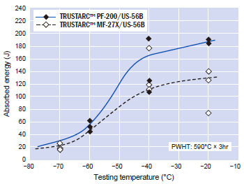
Figure 3: Comparison of notch toughness between fused
flux and bonded flux.
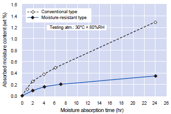
Figure 4: Comparison of moisture absorption rates between
conventional and moisture-resistant coverings.
Another basic design concept is to consider neutron irradiation embrittlement and induced radioactivity resistance in relation to both weld metal and base metal. Because neutron irradiation embrittlement occurs in the belt line region of RPVs during operation, it is an important factor for not only steel but also weld metal. Cu and P, which enhance neutron irradiation embrittlement and such elements with high induced radioactivity as Co and Nb are reduced as low as possible. As a matter of fact, Non-Cu-coated SAW wires are now available.
The inner surfaces of an RPV, SG and the primary side piping constitute a severe corrosive environment due to the circulating cooling water contaminated with radioactive elements. The inner surface, in direct contact with the coolant, is overlay-welded with welding consumables for stainless steels or Ni-base alloys in order to protect it from corrosion.
On the shell and end plate inner surfaces of a large RPV, the efficient SAW or ESW mode overlay welding with strip electrode is applied. On the inner surfaces of pipes and nozzles, GTAW and GMAW are used. The concepts and the processes of overlay welding with strip electrode in the two modes are shown in Figures 5 and 6, respectively. The ESW mode is characterized by shallow penetration that reduces dilution by the base metal, thereby providing a low carbon weld with better corrosion resistance. The SAW mode offers low heat input due to faster welding speed; hence, it is a more favorable process for the base metal, which is susceptible to under-clad cracking (UCC).
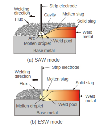
Figure 5: Concepts of overlay welding processes
(SAW and ESW) with strip electrodes.
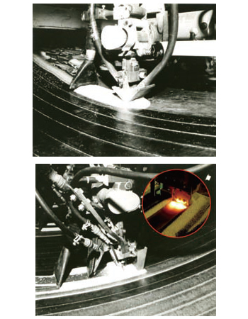
Figure 6: SAW process (left) and ESW process in
operation
on the inner surface of pressure vessels.
Table 7 shows fluxes and strip electrodes for 304L weld metal by SAW and ESW mode overlay welding and the typical chemistries and ferrite numbers (FN per WRC diagram) of overlaid weld metals.
Table 8 shows SMAW and GTAW consumables for 304L overlay weld metal and the chemistries of the undiluted deposited metal. Table 9 shows Ni-base alloy welding consumables for SMAW and GTAW and the chemical and mechanical properties of undiluted deposited metal.
| Process | SAW | ESW | ||
|---|---|---|---|---|
| Single layer*1 | 2nd layer | Single layer*1 | 2nd layer | |
| Trade desig.*2 |
PF-B1/US- BQN309L |
PF-B1/US- BQN308L |
PF-B7FK/US- BQN309L |
PF-B7FK/US- BQN308L |
| AWS class. |
A5.9 EQ309L |
A5.9 EQ308L |
A5.9 EQ309L |
A5.9 EQ308L |
| Polarity | DCEP | DCEP | DCEP | DCEP |
| C (%) | 0.030 | 0.028 | 0.018 | 0.015 |
| Si | 0.67 | 0.65 | 0.53 | 0.54 |
| Mn | 1.14 | 1.05 | 1.36 | 1.14 |
| P | 0.018 | 0.019 | 0.017 | 0.020 |
| S | 0.004 | 0.005 | 0.002 | 0.004 |
| Cu | 0.04 | 0.05 | 0.05 | 0.03 |
| Ni | 12.65 | 10.21 | 12.80 | 10.35 |
| Cr | 23.05 | 19.75 | 23.65 | 19.87 |
| V | 0.05 | 0.04 | 0.05 | 0.04 |
| Co | 0.04 | 0.04 | 0.04 | 0.04 |
| N | 0.041 | 0.019 | 0.048 | 0.020 |
| FN*3 | 12 | 9 | 15 | 11 |
| *1 For a single layer process or underlayer in a multilayer process. *2 Strip size available: 0.4 mm thick × 25, 50, and 75 mm wide. *3 Per WRC diagram. |
||||
| Process | SMAW | GTAW | ||
|---|---|---|---|---|
| Trade desig. |
NC-39L | NC-38L | TG-S309L | TG-S308L |
| AWS class. |
A5.4 E309L-16 |
A5.4 E308L-16 |
A5.9 EQ309L |
A5.9 EQ308L |
| Polarity | DCEP or AC |
DCEP or AC |
DCEP | DCEP |
| C (%) | 0.023 | 0.029 | 0.012 | 0.007 |
| Si | 0.51 | 0.20 | 0.41 | 0.36 |
| Mn | 1.56 | 1.44 | 1.74 | 1.91 |
| P | 0.021 | 0.019 | 0.009 | 0.016 |
| S | 0.003 | 0.004 | 0.003 | 0.003 |
| Cu | 0.03 | 0.03 | 0.02 | 0.02 |
| Ni | 12.46 | 10.24 | 12.29 | 10.26 |
| Cr | 23.92 | 20.31 | 23.76 | 19.86 |
| V | 0.05 | 0.05 | 0.05 | 0.05 |
| Co | 0.04 | 0.04 | 0.05 | 0.02 |
| N | 0.053 | 0.050 | 0.048 | 0.043 |
| FN*1 | 16 | 8 | 14 | 9 |
| *1 Per WRC diagram. | ||||
| Process | SMAW | GTAW |
|---|---|---|
| Trade designation | NI-C703D | TG-S70NCb |
| AWS classification | A5.11 ENiCrFe-3 | A5.14 ERNiCr-3 |
| Polarity | DCEP | DCEP |
| C (%) | 0.06 | 0.02 |
| Si | 0.34 | 0.18 |
| Mn | 6.55 | 2.93 |
| P | 0.004 | 0.001 |
| S | 0.003 | 0.002 |
| Ni | 69.40 | 71.64 |
| Cr | 13.21 | 20.20 |
| Nb+Ta | 2.00 | 2.33 |
| Fe | 7.90 | 1.50 |
| Ti | 0.01 | 0.55 |
| Co | 0.03 | 0.02 |
| 0.2%YS (MPa) | 360 | 370 |
| TS (MPa) | 620 | 680 |
| El (%) | 45 | 40 |
| IV at –196°C (J) | 110 | 150 |
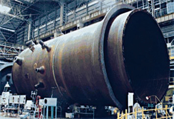
Reactor pressure vessels require an integrated manufacturing
technique wherein base metals are matched with welding
consumables of high and consistent quality.
References:
[1] Kobe Steel: Welding Technical Report, Vol.49 2009-4.
[2] Kobe Steel: Welding of Nuclear Power Equipment, 1990.
Products
- Main Products
- Welding Consumables
- Arc welding robots
- Industries - Recommended Materials
- Welding Handbook Quick View
- Product Quick View & Highlights
- For HEAT-RESISTANT STEEL
- For STAINLESS STEEL
- For LOW-TEMPERATURE STEEL
- Product Highlight
- Catalog
- Technical Highlights
- Certification
- SDS ※English Only
- ARCMAN
- Welding Robot
- Software


