

- Home >
- Products >
- Technical Highlight >
- Vol.10: Total welding solutions: Integrating Kobelco’s comprehensive technologies >
Technical Highlight Vol.10
Total welding solutions: Integrating Kobelco’s comprehensive technologies
1 Preface
A solution is the act of or capability for solving problems. When it comes to a welding solution, it means solving customers’welding problems. In the course of helping clients solve problems and addressing their requests, Kobe Steel, Ltd. has been able to develop its highly reputed range of welding consumables, robotic welding systems as well as welding power sources and processes. The basis of all welding solutions arises from the users’needs, as shown in Figure 1.
In the past, however, a welding consumable or a robotic welding system was regarded as the endpoint of welding product development, and it would be up to the customer to adopt the product or combine one final product with another. The total welding solution as envisaged by Kobe Steel seeks to define the entire welding procedure, matching the welding process with the appropriate welding consumable, shielding gas, and power source. Ultimately the goal is to raise the quality of welded structures by improving the efficiency of the welding procedure and reducing costs (Figure 2).
Kobe Steel, Ltd. is one of the few companies in the world that develops and manufactures welding consumables, robotic welding systems and power sources. This enables Kobe Steel to offer its original welding consumables in combination with the most appropriate welding procedures. In this special edition of Kobelco Welding Today, we wish to introduce three new total welding solutions: MX-MIG process, J-Solution™ Zn and Ultra High Current MAG Welding.
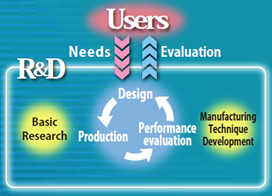
Figure 1: Welding solution cycle
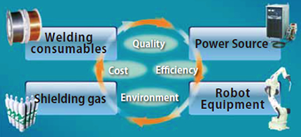
Figure 2: Solution diagram and its factors related to welding procedure
2 MX-MIG process
| Figure 3: Bead appearance | Figure 4: Macrostructure |
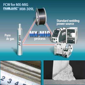
MX-MIG is a total welding solution that combines the MIG welding process with pure Ar shielding gas, MM-309L flux cored wire (FCW) and an inexpensive, standard welding power source. Ar shielding gas can decrease C content in the weld metal, reduce spatter and fumes, and allow low dilution overlay welding due to shallow penetration, while MM-309L is specially designed to maintain an appropriate amount of oxygen in the molten pool.
The Product Spotlight of Kobelco Welding Today; No. 16-2 introduced MX-MIG as a process for welding in automobiles, in which MM-1S FCW for general carbon steels, is used for lap-fillet weld joints on thin steel plates. This article explains the same process for stainless steels.
MM-309L is 309L FCW for the MX-MIG process. By adjusting the flux, MM-309L is designed to improve bead wetting at the toe area, which can be problematic with pure Ar gas. (See Figure 3 and Figure 4.)
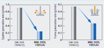
| Figure 5: Spatter generation rate | Figure 6: Fume emission rate |
2-1. Generation rate of spatter and fumes
As seen in Figure 5 and Figure 6, MM-309L reduces spatter to one-third or less and fume emissions by half that of the conventional DW-309L.
2-2. Chemistry and mechanical properties
The chemistry and mechanical properties of MM-309L all deposited metal are shown in Tables 1 and 2 respectively.
| C | Si | Mn | P | S | Ni | Cr | Mo | NW*1 |
|---|---|---|---|---|---|---|---|---|
| 0.02 | 0.77 | 1.23 | 0.013 | 0.002 | 13.7 | 24.5 | 0.02 | 17.7 |
| Note: *1 FNW: Ferrite content according to WRC diagram | ||||||||
| 0.2%PS | TS | EI | vE(-20℃ ) | vE(-196℃) |
|---|---|---|---|---|
| 427MPa | 563MPa | 36% | 40J | 21J |
2-3. Low dilution overlay welding
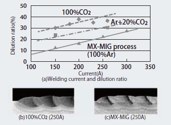
Figure 7: Penetration shape and base metal dilution ratio
The pure Ar gas used for the MX-MIG process increases the arc range and reduces the energy density over the molten pool surface, thus allowing shallow penetration of the base metal, as shown in Figure 7(c). Figure 7(a) shows the influence of the shielding gas and welding current on the base metal dilution ratio. The base metal dilution ratio of the MX-MIG process is below 20% at 200A and below 30% at 300A.
It is clear that the MX-MIG process allows low dilution overlay welding even with high current/high deposition welding and thus reduces the number of welding passes as well as working time.
2-4. Overlay welding
Overlay welding was carried out with DW-309L and MM-309L, using a welding speed of 30cm/min for three passes in one layer and by changing the welding current as shown in Table 3. It shows that the chemistries of both the overlay weld metal and the first layer are equivalent to those of 308L stainless steel even at 250A.
MM-309L resulted in shallow base metal penetration 〔as seen in Figure 8(b)〕 as well as excellent bead appearance and slag removal.
| Product name |
Welding current |
C | Si | Mn | Ni | Cr | N | FNS*1 |
|---|---|---|---|---|---|---|---|---|
| DW- 309L |
150A | 0.06 | 0.62 | 1.26 | 9.1 | 17.7 | 0.021 | 3.0 |
| 200A | 0.06 | 0.57 | 1.28 | 8.8 | 17.3 | 0.019 | 2.3 | |
| 250A | 0.06 | 0.53 | 1.31 | 8.7 | 17.2 | 0.020 | 1.1 | |
| 300A | 0.07 | 0.50 | 1.26 | 8.6 | 16.9 | 0.019 | 1.0 | |
| MM- 309L |
200A | 0.03 | 0.74 | 1.19 | 12.4 | 22.2 | 0.021 | 9.5 |
| 250A | 0.04 | 0.71 | 1.21 | 11.2 | 20.2 | 0.019 | 6.9 | |
| 300A | 0.05 | 0.69 | 1.22 | 10.5 | 18.7 | 0.019 | 3.6 | |
| Note: *1 FNS: Ferrite content according to Schaeffler diagram | ||||||||
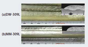
Figure 8: Bead appearance and penetration shape
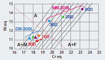
Figure 9: Microstructure change of overlay-weld metal
Figure 9 is a DeLong Diagram based on Table 3. In the case of DW-309L, all four results indicate a mixed austenitic and martensitic microstructure (A+M) that could crack at the hardened zone. On the other hand, the all results obtained with MM-309L show a mixed austenitic and ferritic structure (A+F) that would enable high current welding. Using MM-309L for overlay welding, one may weld a first layer with a high current range like 300A, while raising welding efficiency as high as 1.6 times, compared with the conventional process that applies a low current below 200 A.
3 J-Solution™ Zn
To prevent rust in automobiles, manufacturers utilize galvanized steel. Unfortunately poor weldability is a well-known drawback of galvanized steel sheet. The zinc (Zn), plated on the sheet surface, evaporates during welding, causing pore defects such as pits (open holes on the weld metal surface) and blowholes (defects inside weld metals) to occur. And another weak point is the increase of spatter because the evaporated Zn gas blows off molten droplets as well as the molten pool itself.
In order to improve weldability, the latest visualizing technology was used to examine the mechanism of Zn gas generation. As a result, Kobe Steel and Daihen have together developed a solution involving Kobe Steel’s new solid wire and Daihen’s current-wave control as well as a new type of shielding gas. Named J-Solution™ Zn, this process resists porosity and reduces spatter.
3-1. Mechanism of Zn gas generation
It has been assumed that Zn gas can generate pits and blowholes if it is emitted into the molten pool right behind the arc but not if it evaporates as it is emitted from just under the arc. Figure 10 indicates the conventional thinking and the assumption in this regard.
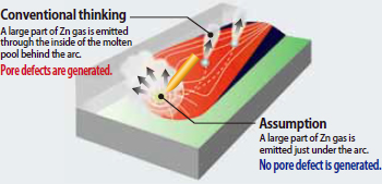
Figure 10: How pore defects are generated
This assumption has recently been studied by observing a moving picture of Zn gas behavior in the molten pool during welding. An X-ray transmission, high-speed moving picture camera was used under the cooperation of the Joining and Welding Research Institute, Osaka University, and proved that the assumption was correct. As shown in Figure 11, Zn gas that remained in the molten pool instead of evaporating from under the arc caused pore defects. On the other hand, when Zn gas largely evaporated from under the arc, pore defects were not generated at all.
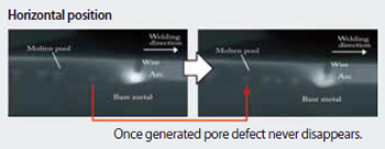
Figure 11: Pore defect behavior in the molten pool, observed through X-ray transmission photograph
When Zn gas evaporates from just under the arc, bubbles do not form in the molten pool and pore defects are avoided. Accordingly it is now clear that the amount of pressure applied to the molten pool right under the arc is the dominant factor allowing Zn gas to evaporate quickly.
3-2. Improvement of porosity resistance
As explained, depressing the molten pool right under the arc is essential to improve porosity resistance. In order to learn how to do this more effectively, all three elements of gas shielded arc welding - welding consumable, shielding gas and welding power source - were examined and the results incorporated into J-Solution™ Zn, which significantly reduces porosity.
3-2-1. FAMILIARC™ MIX-Zn solid wire
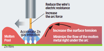
Figure 12: Influential factors depressing the molten pool
In order to exert sufficient pressure on the molten pool just under the arc, the flow of the molten pool right under the arc must be minimized. The factors influencing this flow are the surface tension of molten pool and the arc force (See Figure 12). For J-Solution™ Zn, the surface tension of the molten pool was increased by reformulating the welding wire chemistry, and the arc force was raised by minimizing the welding wire’s electric resistance; thus high current welding that maintains the wire’s melting rate has become possible.
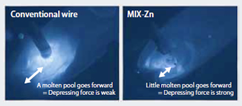
Figure 13: Molten pool shape
(flat position welding with an electrode inclined 30°
MIX-Zn solid wire was developed to optimize surface tension as well as to apply a higher current with the same deposition amount by reducing the wire’s electric resistance.
The photos in Figure 13 of molten pools just under the arc with conventional solid wire and MIX-Zn show that MIX-Zn depresses the molten pool and prevents gravity from moving it forward.
3-2-2. Shielding gas
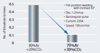
Figure 14: Effect of shielding gas composition against porosity resistance
Whereas pulsed MAG welding generally applies Ar+20%CO2 gas, which reduces spatter through spray transfer, J-Solution™ Zn process has adopted Ar+30%CO2 gas because of its effect on the arc force that allows tension on the surface of the molten pool to be maintained while also keeping spatter low. The mere 10% increase of CO2 gas has a remarkable effect on porosity resistance, as seen in Figure 14.
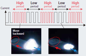
Figure 15: Theory of pulse wave function
3-2-3. Pulse wave function
The low frequency-superimposed pulse wave (pulse wave function) is applied in order to either strengthen or weaken the arc force, as seen in Figure 15. The periodic change of current produce a pulse wave that sways the molten pool forward and backward, which allows Zn gas to be emitted as the molten pool begins to thin.
3-3. Reduction of spatter
In theory, the application of Ar+30%CO2 as well as Zn gas emissions can make spatter generation worse. However, the intensity of spatter generation depends on the speed and stability of the molten droplets as they detach from the wire end. Here are two methods that can keep spatter to a minimum.
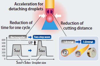
Figure 16: Method of reducing spatter
3-3-1. DP400R welding power source
The first method for removing droplets from the wire end is to produce an electro-magnetic pinch effect by maintaining the welding current. As shown in Figure 16, a two-step pulse wave control is applied. The first peak current is set high to constrict the droplet while the second peak current, set low, causes it to detach slowly from the wire end, resulting in the stable transfer of small sized droplets.
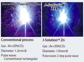
Figure 17: Effect of reducing spatter
3-3-2. Thin diameter wire
The second method for removing droplets from the wire end is to utilize 1.0 mm wire instead of the conventional 1.2 mm. As for efficiency, 1.0 mm diameter is sufficient from a welding speed below 120cm/min, which is common in welding galvanized steel sheets up to 3 mm in thickness. Figure 17 clearly shows the reduction of spatter with the thinner diameter wire.
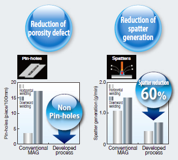
Figure 18: Effect of J-Solution™ Zn
In summary, J-Solution™ Zn represents a new concept in welding procedures that both improves porosity resistance and reduces spatter. While both aims may appear incompatible in a conventional method (i.e. decreasing porosity may increase spatter), the combination of 1.0 mm MIX-Zn, chemically formulated for galvanized steel sheets; Digital-Pulse DP400R, with added new control software and parameter; and Ar+30%CO2 shielding gas allows both issues to be solved together.
If changing the gas composition to Ar+30% CO2 or the wire diameter to 1.0mm is not easy, MIX-GZn is available with Ar+20% CO2 gas. While such excellent results as described above cannot be expected, the results will be far better than those obtained via the conventional procedure.
4 Ultra High Current MAG Welding Process
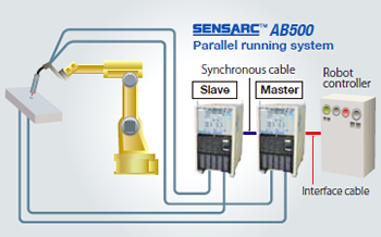
Figure 19: Schematic diagram of Ultra High Current MAG
Process
Combined with FCW and two power sources, Ultra High Current MAG Welding provides a total welding solution for mid-thick plate welding. The process was introduced in the Product Spotlight of Kobelco Welding Today, No.16-3. Here we analyze arc stability with a welding current over 500A and describe the system’s specifications as well as the test results of butt joint welding. A diagram and specifications are shown in Figure 19 and Table 4, respectively.
| Manipulator | ARCMAN™ MP | |
|---|---|---|
| Power source SENSARC™ AB500 Parallel system |
Rated output current | 700A |
| Usage rate | 100% | |
| Load voltage | 55V | |
| Wire feeding rate | Max. 30.0m/min | |
| Welding torch RTW601 |
Rated current | 600A |
| Usage rate | 100% | |
| Cooling method | Water | |
| Welding wire | Product name | MX-A100D |
| Diameter | 1.4mmΦ | |
| Deposition rate | Max. 300g/min | |
| Shielding gas | Ar+20%CO2 | |
4-1. FAMILIARC™ MX-A100D
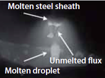
Figure 20: Droplet transfer
In conventional high current MAG welding with a solid wire, rotating transfer of the droplet can cause heavy spatter. In contrast, MX-A100D FCW minimizes spatter. Because the outer steel sheath melts first and the inner flux remains in a columnar state, spray transfer occurs at the wire end instead of rotating transfer (See Figure 20).
| Conventional process *1 |
Developed process |
||||||
|---|---|---|---|---|---|---|---|
| Layer *2 | 1 | 2 | 3 | 4 | 1 | 2 | 3 |
| Welding current (A) | 320 | 360 | 360 | 360 | 530 | 530 | 390 |
| Deposition rate (g/min) |
88 | 101 | 101 | 101 | 255 | 255 | 153 |
| Welding speed (cm/min) |
32.0 | 28.0 | 24.0 | 19.0 | 48.0 | 37.0 | 25.0 |
| Ratio of weld efficiency |
1 | 1.8 | |||||
| Note: *1: MAG welding with solid wire (dia.:1.4mmΦ) *2: One pass/ layer welding 3: Groove shape: 50° single V, 5mm root gap, 16mm thick |
|||||||
4-2. SENSARC™ AB500
The AB500 power source is designed to provide periodic low current by controlling the waveform of the welding current and the arc voltage, resulting in a stable arc voltage equal to the arc length - even under conditions of ultra high current welding.
4-3. Butt joint properties
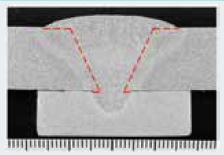
Figure 21: Macrostructure
Figure 21 shows the macrostructure and Table 5, the butt joint properties of the conventional process and Ultra High Current MAG Process.
An additional advantage of this process is the reduction of nitrogen (N2) in the weld metal because the stable spray transfer even at high current range reduces the intrusion of atmospheric N2.
5 Postscript
This article has explored three total welding solutions that consist of dynamic combinations of welding consumables, welding systems, shielding gas and welding power sources. Kobe Steel will continue to pursue solutions to the problems that hinder welders and package the best of them into Kobelco’s total welding solutions.
Products
- Main Products
- Welding Consumables
- Arc welding robots
- Industries - Recommended Materials
- Welding Handbook Quick View
- Product Quick View & Highlights
- For HEAT-RESISTANT STEEL
- For STAINLESS STEEL
- For LOW-TEMPERATURE STEEL
- Product Highlight
- Catalog
- Technical Highlights
- Certification
- SDS ※English Only
- ARCMAN
- Welding Robot
- Software


