

- Home >
- Products >
- Technical Highlight >
- Vol.12: Advanced MAG and MIG Welding Wires : Meeting Car Manufacturing Requirements for Fast and Efficient Welding >
Technical Highlight Vol.12
Advanced MAG and MIG Welding Wires : Meeting Car Manufacturing Requirements for Fast and Efficient Welding
Because people around the world have been demanding that the automobile industry stop polluting the environment and wasting natural resources, in recent years car manufacturers have responded with new engine technologies and lighter auto bodies that improve fuel efficiency.
The need to reduce auto body weight has led to the application of thinner carbon steels and high tensile strength (HT) steels or light materials such as aluminum alloys as well as to the development of new welding consumables and processes that match the newstructural materials. At the same time, car manufacturers have continued to request the welding industry to boost productivity and efficiency, such as by minimizing the need for repairs and reducing spatter, and thereby cut costs.
This article introduces the up-to-date arc welding processes and consumables for various carbon steels and stainless steels that have been developed by Kobe Steel and applied in automobile manufacturing.
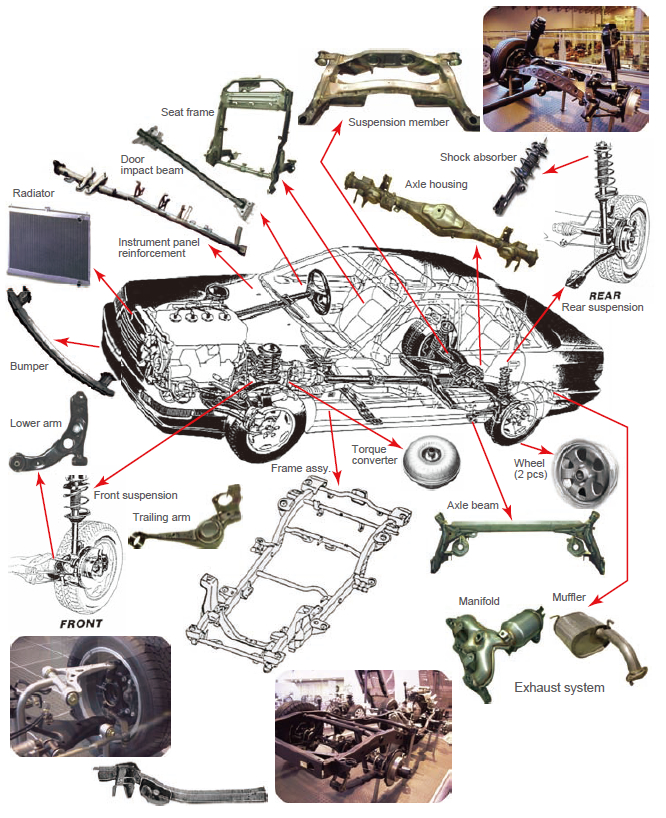
Figure 1: MAG and MIG welding applications of various car parts
Requirements for arc welding wires for car production
As for welding in car production, arc welding and resistance spot welding are the two most common welding processes. Among various arc welding processes, MAG welding (with CO2, Ar-CO2, or Ar-O2) and MIG welding (with Ar or A r-O2) are generally used for car production due to their high deposition efficiency and easy automation for robotic welding. These arc welding processes will continue to be favored in car production. Figure 1 shows how these welding processes are applied to car parts. They are especially favored in parts of the undercarriage, the exhaust system and for complicated shapes where more reliable strength, varied joint configuration, and good root-gap tolerance are essential.
Arc welding wires used in car production also must be resistant to burn-through and capable of high speed welding, both of which are quite important for welding very thin plates.
SE (Smooth & Ecology) wires shine in car production
The SE wires for MAG welding, developed by Kobe Steel, feature as pecial surface treatment instead of a copper (Cu) coating as seen in Figure 2. The SE wire has widely been accepted by car manufacturers as the welding wire that meets their needs.
Table 1 lists the particular SE and Cu-coated wires used for carbon steel welding in the production of various car parts. Table 2 breaks down the chemical compositions of all weld metals deposited by these wires.
| Car parts | Steel type (Plate thick., mm) | Welding process | Trade designation | Wire dia.(mm) |
|---|---|---|---|---|
| ▪Frame assembly ▪Arm (lower & upper) ▪Axle beam ▪Axle housing ▪Torque converter |
Carbon steel plate (2.3-4.0) | MAG (CO2) | SE-50T MG-50T, MG-51T |
1.2 |
| MAG, MAG-P*1 |
SE-A50 MIX-50 SE-A50S MIX-50FS SE-A50FS |
|||
| ▪Axle housing for truck | Carbon steel plate (3.2-6.0) | MAG (CO2) | MG-50 | 1.2-1.6 |
| ▪Impact beam ▪Bumper reinforcement |
Carbon steel tube & plate (1.4-2.3) | MAG (CO2) | SE-50T MG-50T, MG-51T |
1.2 |
| MAG, MAG-P*1 |
SE-A50 MIX-50 |
|||
| ▪Suspension member (Cross-member) |
Carbon steel plate (1.6-2.6) | MAG (CO2) | SE-50T MG-50T, MG-51T |
1.2 |
| MAG, MAG-P*1 |
SE-A50 MIX-50 |
|||
| Galvanized steel plate (1.6-2.6) | MAG (CO2) | SE-50T MG-1Z MX-100Z *3 |
1.2 | |
| MAG-P*1 | SE-A1TS MIX-1TS, MIX-1Z |
|||
| Corrosion resistant steel plate1(1.6-2.6) | MAG-P*1 | SE-A1TS MIX-1TS |
||
| ▪Instrument panel reinforcement ▪Seat frame |
Carbon steel plate (0.8-1.6) | MAG (CO2) | SE-50T MG-50T, MG-51T |
0.8-1.0 |
| MAG | SE-A50 MIX-50 |
|||
| MAG (CO2), MAG*2 |
MG-1SP | 1.2 | ||
| ▪Body exterior plate ▪Pillar reinforcement |
Galvanized steel plate (0.6-1.0) | MAG*2 | MIX-1T | 0.6-0.9 |
| *1: MAG-P signifies pulsed MAG. *2: MAG with variable polarity power source. *3: MX-100Z is a metal-type flux-cored wire (FCW). |
||||
| Trade desig. | Shielding gas | AWS class. JIS class.*1 |
Chemical composition (wt%) | |||||
|---|---|---|---|---|---|---|---|---|
| C | Si | Mn | P | S | Ti+Zr | |||
| SE-50T | CO2 | - Z3312 YGW12 |
0.07 | 0.49 | 1.02 | 0.008 | 0.016 | - |
| MG-50T | 0.09 | 0.44 | 0.96 | 0.012 | 0.012 | - | ||
| MG-51T | A5.18 ER70S-6 Z3312 YGW12 |
0.10 | 0.88 | 1.56 | 0.011 | 0.012 | - | |
| MG-50 | A5.18 ER70S-G Z3312 YGW11 |
0.08 | 0.51 | 1.10 | 0.010 | 0.010 | 0.05 | |
| MIX-1T | Ar-CO2 | - Z3312 G43A2M16 |
0.06 | 0.47 | 0.98 | 0.010 | 0.017 | - |
| SE-A50 | A5.18 ER70S-G Z3312 YGW16 |
0.06 | 0.62 | 1.27 | 0.010 | 0.015 | - | |
| MIX-50 | A5.18 ER70S-3 Z3312 YGW16 |
0.10 | 0.55 | 1.11 | 0.012 | 0.011 | - | |
| SE-A50S | - Z3312 YGW15 |
0.08 | 0.35 | 1.06 | 0.009 | 0.011 | 0.02 | |
| MIX-50FS SE-A50FS |
- Z3312 G49A0M0 |
0.04 | 0.70 | 1.20 | 0.010 | 0.060 | - | |
| MG-1Z | CO2 | A5.18 ER70S-G Z3312 G49A0C12 |
0.10 | 0.49 | 1.19 | 0.009 | 0.009 | - |
| MX-100Z *1 | A5.20 E71T-1C Z3313 T49J0T15-1CA-U |
0.10 | 0.40 | 1.55 | 0.025 | 0.012 | - | |
| SE-A1TS MIX-1TS |
Ar-CO2 | - Z3312 G49A2M16 |
0.08 | 0.60 | 1.01 | 0.010 | 0.006 | - |
| MIX-1Z | - Z3312 G43A2M0 |
0.05 | 0.18 | 1.00 | 0.010 | 0.004 | - | |
| MG-1SP | CO2, Ar-CO2 |
- Z3312 G49A0C11 |
0.06 | 0.58 | 1.32 | 0.010 | 0.015 | ≥0.04 |
| *1: MX-100Z is a metal-type flux-cored wire (FCW). | ||||||||
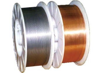
Figure 2: SE wire (left) and Cu-coated wire (right) differ markedly in appearance.
SE wires are “Smooth” in that they offer smooth wire feeding, a smooth arc start, a stable arc, little spatter generation, and a wide welding parameter range due to the special surface treatment that eliminates the need for Cu coating. The benefit of smooth wire feeding allowed by SE-A50 w as d emonstrated by comparing it with a Cu-coated wire at a customer site (see Figure 3); that is, use of SE-A50 resulted in lower consumption of contact tips. In addition, as shown in Figure 4, there were fewer arc start errors with SE-A50 in comparison with a Cu-coated wire that was often suffered from burn-back causing fusion with the contact tip and thus much more arc-start errors.
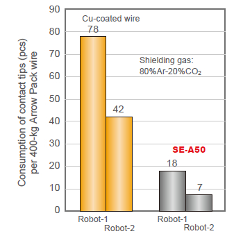
Figure 3: On-site survey records about the consumption of
contact tips in robotic arc welding in comparison between
Cu-coated wire and SE-A50.
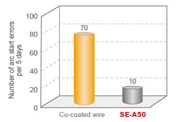
Figure 4: On-site survey records about the number of arc start errors in robotic arc welding in comparison between Cucoated wire and SE-A50
With regard to arc stability, SE wire is also preferable to Cu-coated wire. Figure 5 shows how smaller and more stable droplet transfer with SE-A50S was observed by a high-speed camera. Furthermore, with SE wire, a wider range of welding current is applicable. This is because the welding current needed for transition from globular arc to spray arc is significantly lower with SE-A50S than with Cu-coated wire as shown in Figure 6.
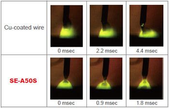
Figure 5: Metal droplet transfer profiles taken by a
high-speed camera in comparison with Cu-coated wire
and SE-A50S (1.2 mmØ, 80%Ar-20%CO2, 260Amp).
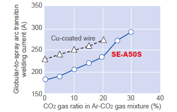
Figure 6: Globular-to-spray arc transition welding current as a function of CO2 ratio in Ar-CO2 shielding gas mixture in comparison between Cu-coated wire and SE-A50S (1.2 mmØ).
SE w ires generate less spatter, as can be seen in the comparison between SE-50T and a Cu-coated wire shown in Figure 7. Larger sizes of spatters by SE-50T are apparently reduced.
In terms of corrosion resistance, SE wire also performs well. Figure 8 shows that corrosion resistance of SE wire is equal to or better than Cu-coated wire after 10% NaCl solution was sprayed on the wire surfaces and left in an atmosphere of 30°C × 80% RH (Relative Humidity) for two hours.
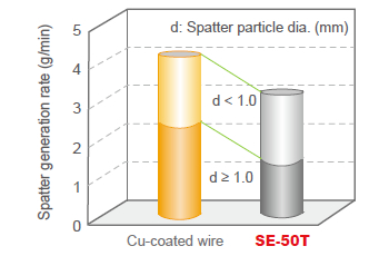
Figure 7: Comparison of spatter generation rates between
Cu-coated wire and SE-50T (1.2 mmØ, CO2, 240 Amp)
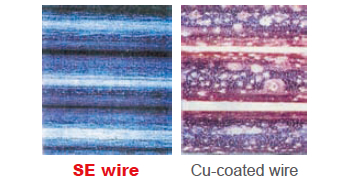
Figure 8: SE wire exhibits excellent corrosion resistance in an accelerated corrosion test (10%NaCl solution spray, 30°C×80%RH, 2 hrs) in comparison with Cu-coated wire
“Ecology” in SE wires relates to the elimination of the Cu coating and the toxic fumes that accompany its use. As seen in Figure 9, SE wire is lower than Cucoated wire in solid waste, CO2 emissions and energy consumption, which factor highly in life cycle assessment (LCA).
SE wire emission of Cu fume is almost zero as shown in Figure 10. It also contributes to achieving a Cu fume PEL (Permissible Exposure Level) of 0.1 mg/m3 as per the OSHA (Occupational Safety and Health Administration) standards.
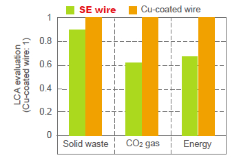
Figure 9: LCA evaluation of Cu-coated wire and SE wire
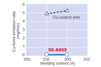
Figure 10: Cu-fume emission rates of Cu-coated wire and SE-A50S
Development of SE-A50FS and MIX-50FS, exclusive wires for car production
The most stringent requirement of car manufacturers is for welding of the highest efficiency without stoppages. High welding speeds of 90-140 cm/min without any welding defect are required; slag generation must also be reduced as slag causes paint to peel off after painting. In order to meet these requirements, SE-A50FS has been developed; also, as its sister product, the Cucoated MIX-50FS has been marketed. These two wires are called FS wires. The advantages of FS wires over conventional wires are discussed below.
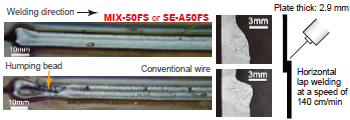
Figure 11: MIX-50FS or SE-A50FS excels in bead contour over conventional wire in high speed welding on thin plate joints.
Good bead contour in high speed welding
FS wire exhibits good bead contour without humping and u ndercut whereas conventional wire results in humped bead, undercut and convex bead ― Figure 11.
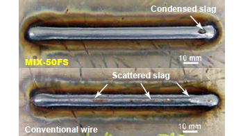
Figure 12: A condensed slag spot with MIX-50FS is easier
to remove over scattered slag with conventional wire.
Little slag generation and easy slag removal
Whereas s lag a ssociated with the FS wire is condensed in one spot, thus easier to remove, but the slag of the conventional wire is scattered along the entire length of bead ― Figure 12.
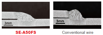
Figure 13: A comparison of cross sectional bead shape between SE-A50FS and conventional wire.
More tolerable to deviated wire-tracking
FS wires offer flat, wide bead shape, which enables to tolerate when wire-tracking deviates from a weld line ― Figure 13.
Unique MAG processes with dedicated wires for specific applications
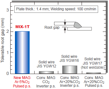
Figure 14: Pulsed MAG (Ar-5%CO2) with MIX-1T outstrips conventional MAG processes in root-gap tolerance.
MIX-1T (1.2 mmØ) with pulsed MAG (Ar-5%O2)
In thin plate welding, conventional MAG processes require to use a s mall-diameter wire of 0 .9-1.0 mm with low welding currents and speeds to prevent burnthrough at the cost of welding efficiency. A new process that combines MIX-1T (1.2 mmØ) and pulsed MAG (Ar-5%O2 shielding gas) has made it possible to weld a 1.4-mm thick plate joint with a 2-mm root gap at speeds as fast as 100 cm/min as shown in Figure 14.
MIX-1T (0.6 mmØ) + variable polarity power source
A variable polarity power source, which makes it easy to change the ratio of electrode positive polarity (EP) and electrode negative polarity (EN), is useful for controlling the penetration and wire melting rate in every weld passes. Ultra-thin plates, such as the 0.6-0.7 mm plates used for car bodies, have generally been spot welded. However, to fulfill recent requirements for increased car body rigidity, arc welding is preferred to use in the place of resistance spot welding.
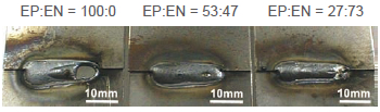
Figure 15: EP:EN polarity ratio of 53:47 resulted in the best bead contour in short-bead welding with MIX-1T of 0.6mmØ (Plate thick.: 0.7 mm; Shielding gas: 80%Ar-20%CO2; Welding parameters: 60A-16V-50cm/min)
Figure 15 shows the test results of MIX-1T (0.6 mmØ) in robotic short-bead welding on 0.7-mm thick plates with a 0.5-mm root gap at three different EP-EN ratios. 100%EP resulted in burn-through; 27%EP-73%EN caused a too narrow bead, and the best result was obtained with 53%EP-47%EN, which has already been applied by one of the biggest Japanese car manufacturers.
SE-A1TS or MIX-1TS with pulsed MAG
The welding of underbody parts such as car suspensions, where galvanized steel plates a re often used to prevent corrosion, requires special care to reduce the spatter and porosity caused by the zinc coating on the surface. Although non-surface-treated corrosionresistant steel plate has i ncreasingly been a dopted for such parts, it often sustains solidification cracks during welding due to the alloying elements of copper and phosphorous contained in the steel plate.
Pulsed MAG with SE-A1TS or MIX-1TS can solve these problems. As shown in Figure 16, pulsed MAG with MIX-1TS offers better bead appearance as opposed to MAG (CO2) welding with conventional wire on a galvanized steel plate. Figure 17 shows the positive influence of MIX-1TS with two types of shielding gases against solidification cracks on the corrosion-resistant steel plate.
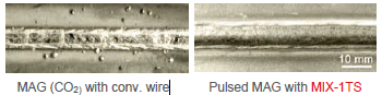
Figure 16: In galvanized plate welding, pulsed MAG with
MIX-1TS results in a good bead look without spatter
adhesion (right) whereas MAG (CO2) welding with
conventional wire exhibits much spatter particles adhered
and porosity (left).
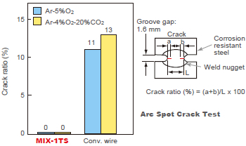
Figure 17: MIX-1TS outstrips conventional wire in solidification crack resistance on corrosion-resistant steel plate.
MAG welding wires for HT steels
One way to reduce car body weight is to apply HT steels with thinner plates. Use of HT steels had been limited to those parts not requiring fatigue strength, such as the bumper, seat f rame, i nstrument panel, and impact members. However, more recently the undercarriage can also be reduced in weight with the application of advanced HT steels of 590, 780 and 980 MPa classes to such parts as the arm, beam, frame and suspensions.
In order for welding wires to meet the requirements of tensile strength and fatigue strength, the MX-MIG process that uses TRUSTARC™ MM-1HS metal-type fluxcored wire has been developed. The process is described in more detail on Page 8 of this issue.
Welding wires for exhaust systems
In car exhaust systems, stainless steel sheets and pipes are applied to exhaust manifolds, converters and mufflers. Because such parts are assembled with thin pipes and press-formed shapes of a wall thickness of 0.8-2.0 mm, the welding joints necessarily contain small or large root gaps. This is why burn-through resistance and root-gap bridging ability are primary concerns for welding wires. Table 3 shows the recommended welding wires for such applications and the chemical compositions of respective all-deposited metals.
MX-A430M metal-type flux-cored wire is excellent in burn-through resistance as seen in Figure 18 and in root-gap bridging ability as shown in Figure 19.
| Trade desig.*1 |
MX-A430M | MG-S430M | MG-S430NbS | MG-S308 |
|---|---|---|---|---|
| AWS class. | - | - | - | A5.9 ER308 |
| Applicable stainless steel grade |
Ferritic | Austenitic | ||
| 430, 409, 410L, 444 | 304 | |||
| Welding process |
MAG (80%Ar- 20%CO2) |
Pulse MIG (98%Ar- 2%O2) |
Pulse MIG (98%Ar- 2%O2) |
Pulse MIG (98%Ar- 2%O2) |
| C (wt%) | 0.05 | 0.02 | 0.02 | 0.05 |
| Si | 0.40 | 0.90 | 0.88 | 0.45 |
| Mn | 0.14 | 0.40 | 0.29 | 1.64 |
| P | 0.008 | 0.021 | 0.023 | 0.024 |
| S | 0.017 | 0.002 | 0.001 | 0.002 |
| Cr | 17.0 | 18.4 | 18.1 | 20.0 |
| Ni | - | 0.23 | 0.21 | 9.8 |
| Nb | 0.75 | - | 0.56 | - |
| *1: MX- is for metal-type flux-core wire whereas MG- is for solid wire. | ||||
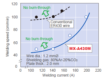
Figure 18: MX-A430M offers a wider currentspeed range over conventional ER430 wire to prevent burnthrough.
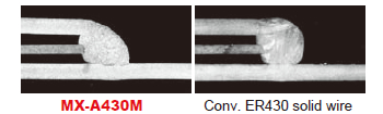
Figure 19: MX-A430M offers better root-gap bridging ability and smoother fusion over conventional ER430 solid wire.
References:
[1] Kobe Steel Welding Technical Reports, Vol. 40 2000-4, -12
[2] Kobe Steel Welding Technical Report, Vol. 46 2006-11
[3] Kobe Steel Engineering Report, Vol. 52
Products
- Main Products
- Welding Consumables
- Arc welding robots
- Industries - Recommended Materials
- Welding Handbook Quick View
- Product Quick View & Highlights
- For HEAT-RESISTANT STEEL
- For STAINLESS STEEL
- For LOW-TEMPERATURE STEEL
- Product Highlight
- Catalog
- Technical Highlights
- Certification
- SDS ※English Only
- ARCMAN
- Welding Robot
- Software


