

- Home >
- Products >
- Technical Highlight >
- Vol.14: A robotic welding system equipped with the REGARC™ process for architectural steel frames >
Technical Highlight Vol.14
A robotic welding system equipped with the REGARC™ process for architectural steel frames
1. Preface
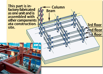
Figure 1: Architectural steel frames using steel pipes for columns
Improving earthquake resistance in buildings is essential in countries prone to strong earthquakes. In Japan, earthquake-resistant design for construction out of wood, steel or reinforced concrete has evolved after many serious earthquakes and is a required feature of architectural design and building fabrication. Steel frame technology for buildings has been a particularly important development in earthquake-resistant design. More than one third of all buildings (including small shops and factories as well as high rise buildings) are made of steel frames, which can account for as much as 60% of a total building. Wood construction is now used primarily for detached houses.
Due to the desire for large spaces in offices or factories, cold-rolled square or circular steel pipes, which do not require diagonal braces, have increasingly been replacing H-section steel columns. Indeed, square steel pipes or circular tubes are now applied in 95% of low and medium-rise structures. These columns and beams are constructed at the steel frame fabricator and transported to and assembled at the construction sites.
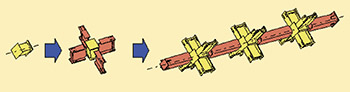
Figure 2: Steel column fabrication process
The standard fabrication process of columns used for architectural steel frames at the fabricator is shown in Figure 2.
A section of a large column is fabricated by first welding the core part (left), then by welding the beams to the column joint (center) and finally by welding the column assembly (right).
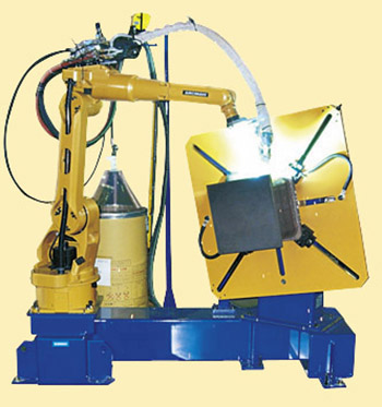
Figure 3-1: Robotic welding system for core parts/ beam
to column joint
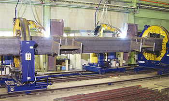
Figure 3-2: Two-joints synchronized robotic welding system
for column assembly
Figure 3: Typical robotic welding systems for architectural
steel frames
Because the welding of the diaphragm to the structural hollow section joint requires much welding and rotationalwork, it is a job for robotic welding. By welding in the flat position, robotic welding provides better efficiency, fewer defects, and smooth and stable beads than semi-automatic welding. Kobe Steel developed a robotic welding system for architectural steel frames in the late 1980s that enjoys a high degree of market share as a result of its high quality and efficiency.
Since the Japanese Building Standard Law was amended after the Great Hanshin Earthquake of 1995, the requirements for the welding of steel structural joints of buildings have become stricter. However, Kobe Steel has developed new systems and functions that increase productivity by means of a synchronized two-joint robotic welding system for column assembly that maintains the heat input limit on each welding joint.
As for the welding process, a standard CO2 gas shielded arc welding process has long been favored for high efficiency as well as lower cost than Ar gas even though high spatter generation has been a well-known drawback. Therefore, Kobe Steel has developed “REGARC™ process” to be used in combination with the new SENSARC™ AB500 power source and FAMILIARC™ MG-50R(N) and FAMILIARC™ MG-56R(N) solid wires.
This process achieves high deposition while minimizing spatter and fumes even with standard CO2 gas shielded arc welding. This article introduces the REGARC™ process and a robotic welding system for architectural steel frames equipped with REGARC™ process.
2. Features of the REGARC™process
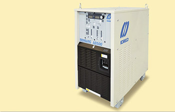
Figure 4: New power source: SENSARC™ AB500
This process utilizes the specially-designed SENSARC™ AB500 power source (see Figure 4), as well as MG-50R(N) or MG-56R(N) solid wire for the robotic welding of architectural steel frames. Table 1 shows the typical deposited metal chemistries of MG-50R(N) and MG-56R(N).
| Product name | JIS classification *1 |
Typical chemistry of deposited metal (mass%) |
|||||
|---|---|---|---|---|---|---|---|
| C | Si | Mn | P | S | Ti+Zr | ||
| MG-50R(N) | Z3312 YGM11 | 0.09 | 0.57 | 1.00 | 0.010 | 0.013 | 0.03 |
| MG-56R(N) | Z3312 YGM18 | 0.06 | 0.48 | 1.33 | 0.009 | 0.007 | 0.03 |
| Note: *1 JIS: Japanese Industrial Standard | |||||||
2-1. Low spatter
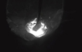
Figure 5-1: Droplet forms
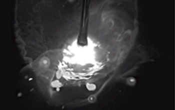
Figure 5-2: Droplet and some molten metal explodes
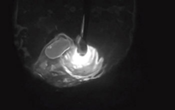
Figure 5-3: Droplet scatters
Figure 5: Globular droplet transfer by conventional process
In conventional CO2 gas shielded arc welding, the metal transfer mode is generally globular transfer, in which large droplets transfer irregularly as the welding current increases. After working on droplet transfer control through pulsed current waveform, Kobe Steel developed the REGARC™ process, which reduces spatter by producing and detaching droplets in regular fashion.
What is the difference in droplet transfer between the conventional process and the REGARC™ process? In the conventional process, a droplet is formed (Figure 5-1) and then short-circuited by the molten pool just before detaching, after which the droplet as well as some of the molten metal explodes right after the arc is re-ignited (Figure 5-2), or when a droplet grows, it is detached while being pushed upward by arc force, and scattered while rotating (Figure 5-3).
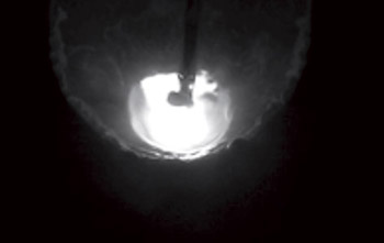
Figure 6-1: Droplet is small and squeezed
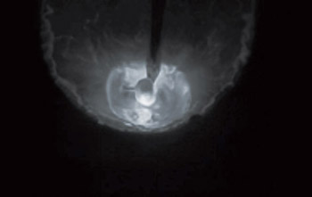
Figure 6-2: Droplet is detached smoothly
Figure 6: Droplet transfer by REGARC™ process
By contrast, in the REGARCTM process, the droplet is squeezed by the pulsed peak current as soon as it forms (Figure 6-1), and then it is detached by the low current during a base duration (Figure 6-2).
The detached droplet is absorbed into the molten pool smoothly. With the timely control of optimum pulsed peak current at the time a droplet forms or detaches, the droplet size remains small and uniform and transfer is smooth.
2-2. High deposition rate and low heat input
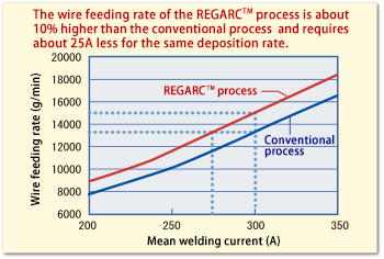
Figure 7: Relationship between mean welding current
and wire feeding rate
Figure 7 shows the relationship between welding current and wire feeding rate (wire melting rate) in the conventional CO2 gas shielded arc welding process and the REGARC™ process.
The wire feeding rate of the REGARC™ process is more than 10% higher than that of the conventional process. Because the pulsing welding current of the REGARC™ process is higher than that of the conventional process, resulting in higher Joule heat, the deposition rate (and overall efficiency) of the REGARC™ process is higher for any amount of welding current (mean value) used.
This means that the REGARC™ process can achieve the same deposition rate with 10% less of the mean welding current required of the conventional process. The deposition rate at 300A in the conventional process is equivalent to that at 275A in the REGARC™ process. This allows for a reduction in heat input, increasing weld metal properties as well as minimizing welding distortion or deforming.
2.3 Good and deep penetration
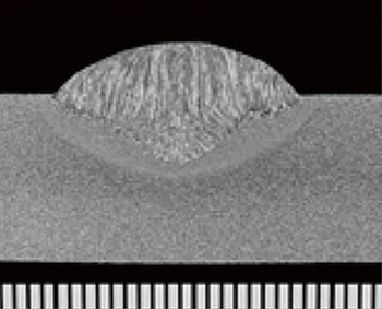
Figure 8-1: Penetration shape by conventional process
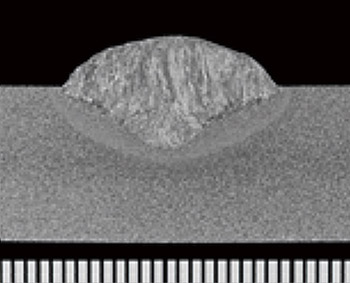
Figure 8-2: Penetration shape by REGARC™ process
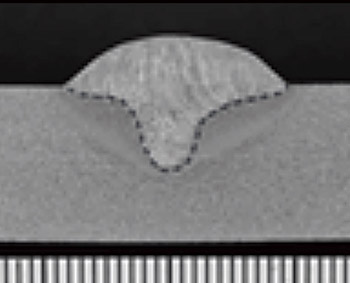
Figure 8-3: Penetration shape by Ar-CO2 mixed gas (Reference)
Figure 8: Difference in penetration shape between
conventional and REGARC™ processes
Figure 8 shows the difference in penetration shape between the conventional and REGARC™ processes while obtaining the same deposition rate.
Even though the mean welding current of the REGARCTM process is lower than that of the conventional process, similar penetration is obtained (Figures 8-1 & 8-2) because of the higher peak current of the REGARCTM process. Hence, it can be seen that sound welding can be performed despite lower heat input.
For reference, Figure 8-3 shows the penetration shape derived from MAG welding using Ar-CO2 mixed gas, which is known as a low spatter welding method. Penetration is finger-shaped, which would be poor in porosity resistance; by contrast, penetration by the REGARC™ process is wide, deep and bowl-shaped, which is porosity- and hot crack-resistant.
2.4 Low fume
The difference in fume emission rate per unit weight of welding wire by the conventional and REGARCTM processes is shown in Figure 9.
It is clear that the REGARCTM process generates nearly half the amount of fumes compared with the conventional process.
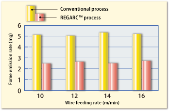
Figure 9: Difference in fume emission rate between the
conventional and REGARCTM processes
3. Robotic welding system for architectural steel frames equipped with REGARC™ process
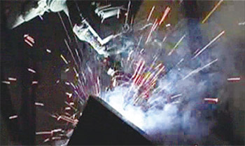
Figure 10-1: Conventional process
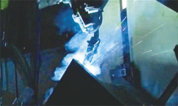
Figure 10-2: REGARCTM process
Figure 10: Difference of spattering during column welding
between the conventional and REGARC™ processes
A robotic welding system for architectural steel frames equipped with the REGARC™ process has the following advantages over the conventional process:
1- Increased productivity by shortening cycle time
2- Improved weld quality
3- Less post-welding work, such as scraping or grinding
4- Better energy savings
Figure 10 clearly shows much less spattering during the welding of a diaphragm to a structural hollow section joint under the REGARC™ process than the conventional process.
Figure 11 compares the two processes in relation to the amount of spatter sticking to a nozzle during the welding of a diaphragm to a structural hollow section joint with single bevel groove. The REGARC™ process can reduce the amount of spatter to one fourth that of the conventional process, even on welding a groove inside.
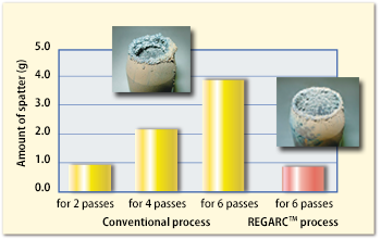
Figure 11: The amount of spatter sticking to a nozzle during
column welding (with a single bevel groove) in
the conventional and REGARC™ processes
When spatter sticks to the inside of a nozzle, shielding may be reduced, resulting in poor mechanical properties as well as welding defects such as weld metal porosity. For this reason, robotic welding incorporates automatic nozzle cleaning and nozzle exchanging in order to maximize operation time.
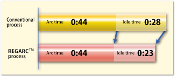
Figure 12: Comparison of cycle time between conventional
and REGARC™ processes
The robotic welding equipped with REGARC™ process reduces the frequency of nozzle cleaning or exchanging to one half so that idle time is minimized. This leads to increased arcing time and shorter cycles.
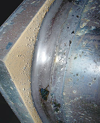
Figure 13-1: Conventional process
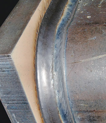
Figure 13-2: REGARC™ process
Figure 13: Comparison of spatter amount on plates
between conventional and REGARC™ processes
Figure 12 compares the results obtained from welding a square tubular steel column with a side length of 400 mm and a plate thickness of 22 mm by the conventional and REGAEC™ processes. The REGARC™ process reduced the cycle time by 10%, and because of less spatter, post-welding scraping and grinding work was also lessened.
Figure 13 compares the welded bead appearance in both the conventional and REGARC™ processes.
Much spatter is visible on the plate surface of the diaphragm as well as the column sides on the piece welded by the conventional process, while very little spatter can be seen on the bead surface of that welded by the REGARC™ process.
As mentioned earlier, the REGARC™ process can save energy because it achieves a higher deposition rate with a lower mean welding current as compared with the conventional process. As much as 5% less electric power may be consumed.
4. Postscript
Highly reputed by customers, the robotic welding system equipped with the REGARC™ process is ready to become the next generation robotic welding system for architectural steel frames in Japan and other parts of the world.
We will continuously develop and propose up-dated welding solutions by approaching from both welding consumables and robotic welding systems.
Products
- Main Products
- Welding Consumables
- Arc welding robots
- Industries - Recommended Materials
- Welding Handbook Quick View
- Product Quick View & Highlights
- For HEAT-RESISTANT STEEL
- For STAINLESS STEEL
- For LOW-TEMPERATURE STEEL
- Product Highlight
- Catalog
- Technical Highlights
- Certification
- SDS ※English Only
- ARCMAN
- Welding Robot
- Software


