

- Home >
- Products >
- Technical Highlight >
- Vol.19: Recent developments of AWS specifications >
Technical Highlight Vol.19
Vol.19: Recent developments of AWS specifications
Traditionally, the American Welding Society (AWS) established its specifications for carbon steel welding consumables separately from those for low alloy steel. AWS specifications for welding consumables were also independent from those of the International Organization for Standardization (ISO). Recently, however, the AWS has changed direction and has begun developing unified specifications. In this article, the latest developments in AWS specifications are discussed.
1. Integration of AWS specifications
As mentioned, AWS specifications for carbon steel and low alloy steel welding consumables had been specified individually until recently. A new move to unify the specifications of the different kinds of welding consumables has been discussed and concrete actions to do so have started, as shown in Table 1.
| Kinds of welding consumables | Conventional specifications | New specifications to be integrated | |
|---|---|---|---|
| Carbon steel | Low alloy steel | ||
| Covered electrode | A5.1 | A5.5 | Planning |
| Solid wire | A5.18 | A5.28 | In preparation |
| Flux cored wire | A5.20 | A5.29 | A5.36 |
In order to unify the specifications, it has been decided to adopt an open classification system in which a welding consumable should be classified by optional selection of such properties as tensile strength, notch toughness testing temperature and chemical composition. One drawback of the conventional system, for example, was that a new product with higher strength than and with the same chemical composition range as a conventional product but without a corresponding classification had to be classified as a grade “G” because of the fixed classification system where the above-mentioned properties were fixed in accordance with classifications.
AWS A5.36/A5.36M:2012 “Specification for Carbon and Low-Alloy Steel Flux Cored Electrodes for Flux Cored Arc Welding and Metal Cored Electrodes for Gas Metal Arc Welding” was published in 2012 as the first integration of two AWS specifications. The schedule to issue integrated specifications of solid wires as well as covered electrodes will be determined, judging from how A5.36 makes progress in becoming familiar.
1.1 Flux cored wires
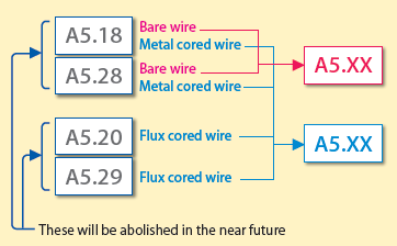
Figure 1: Integration scheme of FCWs and solid wires
A5.36 published in 2012 is currently under modification in order to prepare for the second edition. It contains not only A5.20 (Specification for Carbon Steel Electrodes for Flux Cored Arc Welding) and A5.29 (Specification for Low-Alloy Steel Electrodes for Flux Cored Arc Welding) but also metal cored wires that were contained in A5.18 (Specification for Carbon Steel Electrodes and Rods for Gas Shielded Arc Welding) and A5.28 (Specification for Low-Alloy Steel Electrodes and Rods for Gas Shielded Arc Welding). Figure 1 shows the integration scheme of flux cored wires (FCWs) including metal cored wires and solid wires (or bare wires).
Figure 2 shows classification and designation according to A5.36. They are to be classified by choosing appropriate properties in each category. However, some classifications and designations, such as E71T-1C, that have widely been used and may cause inconveniences if suddenly abolished, may continue to apply the conventional fixed classification system (see Table 2). It was planned at the beginning that A5.20 and A5.29 would be abolished and transferred to A5.28 in 2015; however, that was changed so that both A5.20 and A5.29 as well as A5.28 may continue to exist because of the delay in the transfer.
Mandatory Classification Designatorsa
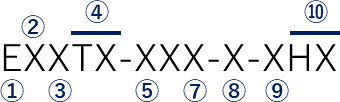
① Designates an electrode.
② Tensile Strength Designator. For A5.36 one or two digits indicate the minimum tensile strength(when multiplied by 10000 psi) of weld metal deposited with the electrode under the welding conditions specified in this specification. For A5.36M two digits are used to indicate the minimum tensile strength (when multiplied by 10 Megapascals [MPa]). See Table 2.
③ Position Designator. This designator is either "0" or "1." A "0" is for flat and horizontal positions only. "1" is for all positions(flat, horizontal, vertical with downward progression, and/or vertical with upward progression and overhead).
④ Usability Designator. This letter is the letter "T" followed by some number from 1 through 17 or the letter "G." The letter "T" identifies the electrode as a flux cored electrode or metal cored electrode. This designator refers to the usability of the electrode with requirements for polarity and general operating characteristics(see Table 4). The letter "G" indicates that the polarity and general operating characteristics are not specified. An "S" appears at the end of this designator when the electrode being classified is intended for single pass welding only.
⑤ Shielding Gas Designator. Indicates the type of shielding gas, if any, used for classification(see Table 5). The letter "Z" in this position indicates that the shielding gas composition is as agreed upon between supplier and purchaser. When no designator appears in this position, it indicates that the electrode is self shielded and that no external shielding gas is used.
⑥ Designates the condition of heat treatment in which the tests were conducted. "A" is for as-welded and "P" is for postweld heat treated. The time and tempereture of the PWHT is specified in 9.2.1.2 and Table 8. The letter "G" in this position indicates that the PWHT procedure is as agreed upon between supplier and purchaser. This designator omitted when the electrode being classified is intended for single pass welding only.
⑦ Impact Designator. For A5.36 this designator indicates the temperature in °F at or above which the impact strength of the weld metal referred to above meets or exceeds 20 ft・℔f. For A5.36M this designator indicates the temperature in °C at or above which the impact strength of the weld metal meets or exceeds 27J. The impact designator may be either one or two digits (see Table 3). A "Z" in this position indicates that there are no impact requirements for the electrode classification. This designator is omitted when the electrode beiing classified is intended for single pass welding only. A "G" in this position indicates the impact requirements are not specified but are as agreed upon between purchaser and supplier.
⑧ Deposit Composition Designator. One, two or three characters are used to designate the composition of the deposited weld metal (see Tabe 6). The letter "G" indicates that the chemical composition is not specified. No designator used in this position when the electrode being classified is a single pass electrode.
Optional Supplemental Designatorsb
⑨ Optional, supplemental diffusible hydrogen designator (see Table 13).
⑩ For flux cored electrodes, the letter "D" or "Q" when preset in this position indicates the weld metal will meet supplemental mechanical property requirements with welding done using low heat input, fast cooling rate procedures and using high heat input, slow cooling rate procedures as prescribed in Clause 16 (see Tables 9 and 10).
a The combination of these designators constitutes the flux cored electrode classification.
b These designators are optional and do not constitute a part of the flux cored or metal cored electrode classification, as applicable.
Figure 2: Classification symbols and designators (Excerpt from AWS A5.36)
| Source Specification for Electrode Classification & Requirements | Classification Designationb,c | Electrode Type | Shielding Gasd | Weld Deposit Requirements | |
|---|---|---|---|---|---|
| Mechanical Propertiese | Weld Depositf | ||||
| AWS A5.20/A5.20M | E7XT-1Cg | Flux Cored | C1 | Tensile Strength: 70 ksi-95 ksi Minimum Yield Strength: 58 ksii Min. Charpy Impact: 20ft-lbf @ 0°F Minimum % Elongation: 22%j | CS1 |
| E7XT-1Mg | M21 | ||||
| E7XT-5Cg | C1 | Tensile Strength: 70 ksi-95 ksi Minimum Yield Strength: 58 ksii Min. Charpy Impact: 20ft-lbf @ -20°F Minimum % Elongation: 22%j | CS1 | ||
| E7XT-5Mg | M21 | ||||
| E7XT-6g | None | GS1 | |||
| E7XT-8g | |||||
| E7XT-9Cg | C1 | CS1 | |||
| E7XT-9Mg | M21 | ||||
| E7XT-12Cg | C1 | Tensile Strength: 70 ksi-90 ksi Minimum Yield Strength: 58 ksii Min. Charpy Impact: 20ft-lbf @ -20°F Minimum % Elongation: 22%j | CS2 | ||
| E7XT-12Mg | M21 | ||||
| E70T-4g | None | Tensile Strength: 70 ksi-95 ksi Minimum Yield Strength: 58 ksii Min. Charpy Impact: Not Specified Minimum % Elongation: 22%j | GS3 | ||
| E7XT-7g | |||||
| AWS A5.18/A5.18M | E70C-6Mh | Metal Cored | M21 | Tensile Strength: 70 ksi minimum Minimum Yield Strength: 58 ksii Min. Charpy Impact: 20 ft-lbf @ -20°F Minimum % Elongation: 22%j | CS1 |
b Under AWS A5.20/A5.20M, the "E" at the beginning of the classification designates an electrode. The "7" is the tensile strength designator. The "X" indicates the electrode's position of welding capability. A "0" is used to indicate flat and horizontal only. A "1" is used to indicate all position capability. The "T" identifies the electrode as a flux cored electrode The one or two digit number after the dash indicates the electrode's usability characteristics as defined in AWS A5.20/A5.20M. For the open classification system introduced in this A5.36/A5.36M specification, the "T" identifies the electrode as either a flux cored or a metal cored electrode. The "T" is combined with a one or two digit number as a part of the alpha-numeric designator for usability. See Table 4. Under AWS A5.18/A5.18M for classification E70C-6M, the "E" designates an electrode. The "70" indicates that the weld deposit will have a minimum tensile strength of 70 ksi. The "C" indicates that the electrode is a composite (metal cored) electrode. The "6" indicates the composition of the weld deposit produced with this electrode. The "M" indicates the type of shielding gas used.
c The electrodes shown in the shaded panels are self shielded.
d See Table 5.
e Mechanical properties are obtained by testing weld metal from the groove weld shown in Figure2. Welding and testing shall be done as prescribed in this specification. The requirements for welding and testing are the same as those given in A5.20/A5.20M. All mechanical property testing for the classifications listed in this table shall be done in the as-welded condition.
f See Table6.
g The "D", "Q", and "H" optional designators, which are not part of the electrode classification designation, may be added to the end of the designation as established in AWS A5.20/A5.20M, i.e., E7XT-XXD, E7XT-XXQ, E7XT-XXHX, E7XT-XXDHX, or E7XT-XXQHX, as applicable. The "J" optional, supplemental designator listed in A5.20/A5.20M is no longer required. The open classification system introduced in this A5.36/A5.36M specification eliminates the need for this designator.
h The "H" optional, supplemental designator, which is not part of the electrode classification designation, may be added to the end of the designation as established in AWS A5.18/A5.18M, i.e., E70C-6MHZ. Provisions for the "D" and "Q" optional, supplemental designators have not been established in A5.18/A5.18M and, as a result, may not be used with the E70C-6M designation. However, that does not preclude their use with metal core electrodes classified utilizing the open classification system under the A5.36/A5.36M specification.
i Yield strength at 0.2% offset.
j Percent elongation is in 2in [50mm] gage length when a 0.500in [12mm] nominal diameter tensile specimen and nominal gage length to diameter ratio of 4:1 is used.
1.2 Solid wires
As shown in Figure 1, a new standard that would allow solid wires specified in both A5.18 and A5.28 to be integrated into one standard is under preparation. As in the case of FCWs, a strategy in which major parts are in open classification but some, in fixed classification, is planned to be approved. It is expected that the newly established standard may be published after 2020.
1.3 Covered electrodes
Although it has not been started yet, there are plans to establish an integrated standard.
2. Harmonization (or Matching) with ISO standards
The ISO standards are renowned worldwide as international standards of welding consumables. Table 3 shows ISO standards for welding consumables established by September 2015. Because AWS participated in establishing these ISO standards, the content of some AWS specifications matches with corresponding ISO standards. This trend whereby a product conforming to an AWS specification can be accepted as one that also conforms to an ISO standard will enable welding consumables to be utilized across borders and may lead to more effective and convenient distribution.
Matching domestic standards/specifications with international ones was one of the aims of the Technical Barriers to Trade (TBT) Agreement that was established and made effective in January 1995 by the World Trade Organization (WTO).
| Mild & fine-grained steel | High tensile strength steel | Heat resistant steel | Stainless steel | Ni & Ni-alloy | Cast iron | Al & Al alloy | Cu & Cu alloy | Ti & Ti alloy | |
|---|---|---|---|---|---|---|---|---|---|
| Covered electrode | ISO 2560 | ISO 18275 | ISO 3580 | ISO 3581 | ISO 14172 | ISO 1671 | - | ISO 17777 | - |
| FCW | ISO 17632 | ISO 18276 | ISO 17634 | ISO 17633 | ISO 12153 | - | - | - | |
| TIG welding consumable | ISO 636 | ISO 16834 | ISO 21952 | ISO 14343 | ISO 18274 | ISO 18273 | ISO 24373 | ISO 24034 | |
| Solid wire | ISO 14341 | ||||||||
| Combination of SAW wire and flux | ISO 14171 | ISO 26304 | ISO 24598 | - | - | - | - | ||
| SAW flux | ISO 14174 | - | - | - | - | ||||
| Shielding gas | ISO 14175 | ||||||||
| Filler rod for gas welding | - | - | - | - | - | ISO 1071 | - | - | - |
2.1 Aluminum
AWS A5.10/A5.10M:2012 “Welding Consumables - Wire Electrodes, Wires and Rods for Welding of Aluminum and Aluminum-Alloys - Classification” has already been established as one that matches with ISO 18273:2004 (the same title).
2.2 Stainless steel
AWS A5.9 is under modification as an AWS specification that matches with ISO 14343:2009 “Welding consumables--Wire electrodes, strip electrodes, wires and rods for arc welding of stainless and heat resisting steels--Classification.”
2.3 Ni alloy
AWS A5.14 is under modification as an AWS specification that matches with ISO 18274:2010 “Welding consumables--Solid wire electrodes, solid strip electrodes, solid wires and solid rods for fusion welding of nickel and nickel alloys--Classification.”
2.4 Cases in which mechanical properties are listed in the requirements
Although the above-mentioned three specifications (Al, stainless steel and Ni alloy) require chemical compositions only, many other specifications for welding consumables list the requirements of mechanical properties. Two cases follow in which the AWS and ISO specifications remain different and unification has not yet been carried out.
2.4.1 Groove configuration for all deposited metal on FCWs and solid wires
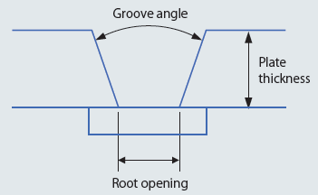
Figure 3: Groove configuration
| AWS | ISO | |||
|---|---|---|---|---|
| Plate thickness (mm) (Example) | 20 | 12 | 20 | 12 |
| Groove angle | 45° | 20° | ||
| Root opening (mm) (Example) | 12 | 6 | 16 | 12 |
Figure 3 shows the groove configuration for all deposited metal on FCWs and solid wires and Table 4, the differences in AWS and ISO specifications.
However, as the difference in groove configurations, as shown in Table 4, is small and has only minor influence on mechanical properties, it is likely that AWS will accept the same groove shape as that of the ISO in the future.
2.4.2 Shape of tensile test specimen for all welding consumables
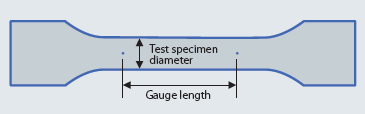
Figure 4: Shape of tensile test specimen
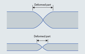
Figure 5: Influence of different gauge length
| AWS | ISO | |||
|---|---|---|---|---|
| Specimen diameter (mm) | 12.5 | 6 | 10 | 8 |
| Gauge length (mm) | 50 | 24 | 50 | 40 |
| Ratio of Gauge length / Specimen diameter | 4 | 5 | ||
Figure 4 shows the shape of a tensile test specimen and Table 5, the difference in specifications.
As seen in Figure 5, if the ratio of gauge length to specimen diameter is different, elongation (%) also changes. Because the deformed part of a small diameter specimen becomes shorter than that of large diameter specimen, the calculated elongation of a small diameter specimen becomes smaller.
3. Postscript
As has been discussed, the AWS has been making progress toward integrating specifications for welding consumables. The details and properties of welding consumables with the same classifications will be easier to recognize under a system of unified specifications.
At the same time, the operation of matching AWS specifications with ISO standards has also been moving forward. It is expected that in the future all welding related specifications will contain the same contents worldwide, and welding consumables of the same quality with the same descriptions will become available from anywhere in the world.
AWS specifications are changing in order to be more useful and utilized more widely in the ways described above.
Products
- Main Products
- Welding Consumables
- Arc welding robots
- Industries - Recommended Materials
- Welding Handbook Quick View
- Product Quick View & Highlights
- For HEAT-RESISTANT STEEL
- For STAINLESS STEEL
- For LOW-TEMPERATURE STEEL
- Product Highlight
- Catalog
- Technical Highlights
- Certification
- SDS ※English Only
- ARCMAN
- Welding Robot
- Software


