

- Home >
- Education Center >
- The ABC’s of Arc Welding >
- Yield Point and 0.2% Offset Yield Strength >
The ABC’s of Arc Welding
Yield Point and 0.2% Offset Yield Strength
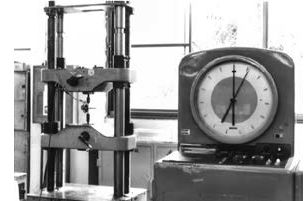
The tensile test can reveal several important engineering properties of materials. These properties are strength (yield point, yield strength, and tensile strength) and ductility (elongation and reduction in area). The strength and ductility of metals are generally obtained from a simple uniaxial tensile test in which a machined specimen is subjected to an increasing load. The stress (load divided by the original cross-sectional area, N/mm2 or MPa) can be plotted against the strain (elongation divided by the original gage length, %) as shown in Figure 1.
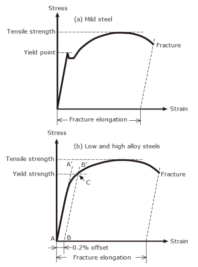
Figure 1: Stress-strain curves for mild steel and low and high alloy steel
The stress-strain curve can vary in configuration according to the properties of the metal tested and the testing temperature. The stress-strain curve of mild steel at room temperature, as in Figure 1(a), displays the point where plastic elongation occurs with no increase in load. This specific point is called the “yield point (or upper yield point).”
By contrast, the stress-strain curve of low alloy steel (e.g. high strength steel and heat-resistant steel) and high alloy steel (e.g. stainless steel) exhibits no such a specific yielding point but produces a smooth curve as shown in Figure 1(b). In this case, the stress required to produce an offset (plastic deformation) amount of 0.2 percent is generally used for the standard strength equivalent to the yield point, which is called “0.2% offset yield strength” or “0.2% proof stress.” Both yield point and 0.2% offset yield strength are often referred simply to as “yield strength” or “yield stress.”
In Figure 1(b) the straight solid portion (the straight modulus line) of Line A-A’ traces the specimen elongation over the original gage length with increasing stress. This linear proportionality between stress and strain represents Young’s modulus (modulus of elasticity) for the metal tested. If the load on this tension specimen is removed at any point along the straight modulus line, then the specimen length will return to its original dimension; thus absolute elasticity is demonstrated by the metal. Note Point B on the strain axis, and draw a line from there to Point B’ parallel to Line A-A’. The point C, where the 0.2% offset line (BB’) intersects the stress-strain curve, is the 0.2% offset yield strength.
As for weld metal, the characteristic of yielding is similar to that of the steel materials mentioned above. That is, filler metals for mild steel (E6019 and E6013) display the yield point on the stressstrain curve of the weld metal, while filler metals for high strength, heat-resistant, and stainless steel exhibit no yield point on their stress-strain curves. Therefore, in the latter case, 0.2% offset yield strength is used as shown for individual brand data in Kobelco Welding Handbook.
Click here for KOBELCO WELDING HANDBOOK
In the design of steel buildings and bridges, yield strength is used for the standard strength to develop the allowable stress according to the specified safety factor. In the case of pressure vessels the allowable stress is developed based on yield strength as well as tensile strength according to the service conditions.
Education Center


