

- Home >
- Education Center >
- Welding References >
- Kinds of welding symbols >
Welding References
1-3. Kinds of welding symbols
| Type of weld | Basic welding symbol |
Remarks |
|---|---|---|
| Double−flanged |  |
――― |
| Single−flanged |  |
――― |
| Square groove |  |
Upset weld, flash weld, and friction weld are included. |
| Single−Vgroove, Double−Vgroove (X groove) |
 |
For an X−groove weld, draw this symbol symmetrically about the reference line for exposition (the reference line). Upset welds,flash welds, and friction welds are included. |
| Single−bevel groove, Double−bevel groove (K groove) |
 |
For a K−groove weld, draw this symbol symmetrically about the reference line. Draw the vertical line of the symbol on the left side. Upset welds, flash welds, and friction welds are included. |
| Single−Jgroove, Double−Jgroove |
 |
For a double−Jgroove weld, draw this symbol symmetrically about the reference line. Draw the vertical line of the symbol on the left side. |
| Single−Ugroove, Double−Ugroove (H groove) |
 |
For an H−groove weld, draw this symbol symmetrically about the reference line. |
| Single−flare−Vgroove, Double−flare−Vgroove |
 |
For a double−flare−Vgroove, draw this symbol symmetrically about the reference line. |
| Single−flare−bevel groove, Double−flare−bevel groove |
 |
For a double−flare−bevel groove weld, draw this symbol symmetrically about the reference line. |
| Fillet weld |  |
Draw the vertical line of the symbol on the left side. For parallel welds, draw this symbol symmetrically about the reference line. For staggered welds, the symbols shown below can be used.
 |
| Plug, Slot |  |
――― |
| Bead, Surfacing |  |
For surfacing, duplicate this symbol side by side. |
| Spot, Projection, Seam |
 |
This symbol represents welds made by electric resistance welding, arc welding, and electron beam welding on lap joints, excluding fillet welds. For a seam weld, duplicate this symbol side by side. If possible, draw the following symbols as specified : |
| Item | Supplementary symbol |
Remarks | |
|---|---|---|---|
| Weld surface shape |
Flat Convex Concave |
 |
Draw the convex symbol outward from the reference line. Draw the concave symbol outward from the reference line. |
| Weld finishing method |
Chipping Grinding Machining Not specified |
 |
For finishing by grinding For finishing by machining No finishing method is specified. |
| Field welding All−around peripheral welding All−around peripheral field welding |
 |
This symbol may be omitted where all− around peripheral welding is obvious. |
|
(1) For welds on the opposite side or the other side of the arrow

(2) For welds on the arrow side or the near side

1-3-2. Examples of welding symbols
| Weld profile | Actual weld joint Welding symbol |
|---|---|
| Field welding The arrow side or the near side |
 |
| The opposite side or the other side of the arrow |
 |
| The arrow side or the near side |
 |
| The opposite side or the other side of the arrow |
 |
| Both sides |  |
| For a root gap of 2mm |  |
| For a root gap of 2mm |  |
| Welds with 16−mm groove depth, 60°groove angle, 2−mm root gap, and 19−mm plate thickness |
 |
| Welds with steel backing : 12−mm plate thickness, 45°groove angle, 4.8−mm root gap, machined for surface finishing |
 |
| Partial penetration weld : 12−mm plate thickness, 5−mm groove depth, 60°groove angle, 0−mm root gap |
 |
| Groove depth : 16mm on the arrow side, and 9mm on the opposite side ; Groove angle : 60°on the arrow side, 90°on the opposite side ; Root gap : 3mm |
 |
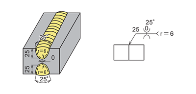
| On both sides : 25−mm groove depth, 25°groove angle, 6−mm root radius, 0−mm root gap |
 |
| T joint with steel backing : 45°groove angle, 6.4−mm root gap |
 |
| Groove depth : 16mm on the arrow side, 9mm on the opposite side ; Groove angle : 45°on the arrow side, 45°on the opposite side ; Root gap : 2mm |
 |
| Fillet welds with different leg length on both sides |
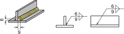 |
| Fillet welds with 6−mm leg length on both sides |
 |
| Parallel welds : 50−mm weld length, 3 welds, 150−mm pitch |
 |
Education Center


