

- Home >
- Education Center >
- The ABC’s of Arc Welding >
- Band-Overlaying: What Overlaying with Strip Electrode Offers >
The ABC’s of Arc Welding
Band-Overlaying: What Overlaying with Strip Electrode Offers
The overlaying with a strip electrode, so-called “Band-Overlaying,” features the use of thin, wide strip electrodes in combination with fluxes instead of wire electrodes for submerged arc welding (SAW) and electroslag welding (ESW) as illustrated in Figure 1. Strip electrodes can utilize two melting modes, depending on the combination of strip electrode and flux: SAW mode and ESW mode. In the former, arc heat melts the strip and flux, while in the latter, Joule resistance heat of the molten slag generated during welding melts the strip.
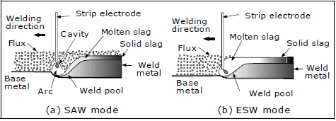
Figure 1: Concept of Band-Overlaying with strip electroden
Both modes efficiently produce a very flat, wide bead corresponding to the width of the strip used, with shallow, uniform penetration into the base metals, compared to the conventional SAW as seen in the Figure 2. The ESW mode provides smaller penetration with better bead shape, resulting in much better corrosion resistance even for the first layer in comparison with the SAW mode. However, SAW mode offers faster welding speeds than the ESW mode. Thus, Band-Overlaying is most suitable for corrosion-resistant overlaying of such stainless steels as 304(L), 316(L) and 347(L), which can be used for shells of oil refining equipment, various kinds of chemical plants and nuclear power plants as illustrated in Figure 3.
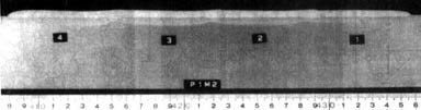
Figure 2: Macrostructure of Band-Overlay weld
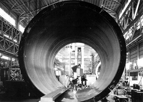
Figure 3: Band-Overlaying of the inside of a shell
As Band-Overlaying adopts direct current for both modes, magnetic blow may cause uneven beads and undercut depending on the position of power cables for the welding head. Earthing has to be duly located at two or more positions. An electromagnetically controlling head, as shown in Figure 4 is another countermeasure to prevent these kinds of defects.
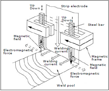
Figure 4: Electro-magnetically controlling welding head for Band-Overlaying
In order to efficiently obtain satisfactory welding results, you should pay attention to the following points:
(1) Thickness of the overlay: 4 to 5 mm
(2) Lap of weld: Around 7 mm
(3) Welding position: Flat or 0.5-1.0 degrees upwardly inclined
(4) Flux burden height: 15-30 mm
(5) Electrode extension: 35-40 mm
| Strip size (0.4T x W mm) |
Current (A) |
Volt (V) |
Speed (cm/min) |
Flux burden height (mm) |
|---|---|---|---|---|
| 25 | 400 | 25 | 14 | 15-25 |
| 50 | 800 | 25 | 14 | 15-25 |
| 75 | 1200 | 25 | 14 | 15-30 |
| 150 | 2400 | 25 | 14 | 15-30 |
Education Center


