

- Home >
- Products >
- Technical Highlight >
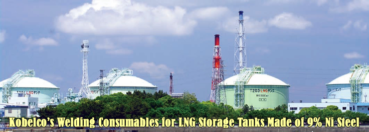
- Vol.2: Kobelco’s Welding Consumables for LNG Storage Tanks Made of 9% Ni Steel >
Technical Highlight Vol.2
![Figure 1: Worldwide LNG imports [1]](../../images/education-center/technical_hightlight/vol02_01.jpg)
Figure 1: Worldwide LNG imports [1]
LNG is Liquefied Natural Gas, in which the main ingredient, methane, is liquefied at the extremely low temperature of minus 161.5 °C. Liquefied natural gas takes up 1/600th the volume of natural gas in a gaseous state, making possible the mass transportation and storage by LNG ships and tanks. Additionally, as natural gas emits 20-40 % less CO2 than other fossil fuels such as petroleum and coal, it is widely considered a form of clean energy. As a result, LNG consumption is forecast to steadily increase as seen in Figure 1, which shows the recent growth of worldwide LNG imports.
9%Ni steel is commonly used for aboveground LNG tanks
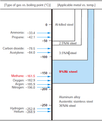
Figure 2: The boiling points of various liquefied gases and
applicable metals for storage tanks.
There are two types of LNG tanks, one for oceangoing LNG ships and the other for onshore storage. As for LNG storage tanks, they can be built either above or below ground. Aboveground tanks usually take the form of a dual shell structure that is cylindrical in shape with a flat bottom, while underground tanks are of the membrane type. Because the inner tank is directly exposed to LNG at minus 161.5 °C, it must have a high level of notch toughness. The inner tanks of aboveground storage tanks are therefore commonly made of 9% Ni steel or aluminum alloy, while those of underground tanks are made of 304 and/or 304L austenitic stainless steels. The choice of material depends on the boiling point of the relevant gas (Refer to Figure 2) because the liquefaction of the gas requires such a particular low temperature.
The rest of this article will introduce aboveground LNG tanks with inner tanks made of 9% Ni steel and discuss related welding consumables and procedures.
![Figure 3: A cross sectional view of PCLNG storage tank [2].](../../images/education-center/technical_hightlight/vol02_03.jpg)
Figure 3: A cross sectional view of PCLNG storage tank [2].
Figure 3 shows an aboveground, flat-bottomed, cylindrical LNG storage tank known as a PCLNG. This structure, widely adopted in overseas countries, has a surrounding wall made of pre-stressed concrete (PC), an outer shell and roof made of low temperature service carbon steel, an inner shell made of 9% Ni steel, and an inner aluminum deck that is suspended from the carbon steel dome roof on the 9% Ni cylindrical shell.
Regulations and standards for LNG tanks
A wide range of regulations and standards define the design, construction, inspection and maintenance of LNG tanks made of 9% Ni steel. Some of the relevant ASME, API, BS EN, and JIS standards are provided below.
(1) ASME Sec. VIII, Div. 1: Design and fabrication of pressure vessels; Div. 2: Alternative rules.
(2) API Standard 620: Design and construction of large, welded, low-pressure storage tanks; Appendix Q: Lowpressure storage tanks for liquefied hydrocarbon gases at temperature not lower than −270°F (−168°C).
(3) BS EN 14620-1(2006): Design and manufacture of site built, vertical, cylindrical, flat-bottomed steel tanks for the storage of refrigerated, liquefied gases with operating temperatures between 0°C and −165°C, Part 1: General.
(4) JIS B8265(2010): Construction of pressure vessel ― General principles; JIS B8267(2008): Construction of pressure vessel.
The most commonly applied regulations and standards worldwide are ASME Sec. VIII and API 620. Table 1 provides a comparison of allowable stresses on aboveground LNG tanks made of 9% Ni steel. Depending on what standard is applied, the allowable stress varies and thus the plate thickness of the shell differs accordingly. As seen in Table 1, ASME and JIS calculate the allowable stress by the strength of the welded butt joint, whereas API uses the strength of the weld metal.
| Code or standard |
Formula to calculate allowable stress |
Standard strength (MPa) |
Allowable stress (MPa) |
|
|---|---|---|---|---|
| API 620 Appendix Q |
Smaller value between 1/3 σBM*1 and 2/3 σYM*2 |
σBM*1 ≥ 660 σYM*2 ≥ 360 |
220 | |
| ASME Sec. VIII |
Div. 1 | 1/3.5 σB*3 | σB*3 ≥ 660 | 190 |
| Div. 2 | 1/2.4 σB*3 | σB*3 ≥ 660 | 280 | |
| JIS | B 8265 | 1/4 σB*3 | σB*3 ≥ 660 | 190 |
| B 8267 | 1/3.5 σB*3 | 190 | ||
| *1: Tensile strength of weld metal. *2: Proof strength of weld metal. *3: Tensile strength of welded butt joint. |
||||
When calculating the allowable stress of 9% Ni steel as per API 620 Appendix Q, the lower value of the strength between the plate (e.g. quenched-and-tempered ASTM A553 Type I: σB ≥ 690 MPa; σY ≥ 585 MPa) and the weld metal (e.g. JIS Z 3225 D9Ni-1: σB ≥ 660 MPa; σY ≥ 360 MPa), namely the strength of the weld metal, is adopted as the standard strength in general. In addition, The Appendix Q allows to use the tensile strength of 690 MPa and the proof strength of 400 MPa as the maximum permitted values for determining the allowable stress, though they must be tested and proven. Thus, API allows adopting the higher strength design, which makes the reduction of plate thickness possible.
In 1960, a destructive test involving a large-sized pressure vessel made of 9% Ni steel was carried out in the USA that proved that 9% Ni steel could be used safely without postweld heat treatment for stress relief. Since then, large capacity tanks made of 9% Ni steel have been constructed widely.
Over time, as tank capacities have been getting larger, the applied plate thickness has also been increasing. While tanks with a capacity of 80,000 kilo liters (kl) would have a 9% Ni steel inner shell with a maximum plate thickness of 30 mm, 140,000 kl tanks require plate that is 40 mm thick. Currently, the design of 200,000 kl tanks is under investigation; these would require plates with thickness of 50 mm, reaching the maximum tank capacity.
Specifications and features of 9% Ni steel
| Standard | ASTM | JIS G 3127 | |||
|---|---|---|---|---|---|
| A353 | A553 Type I |
SL9N 520 | SL9N 590 | ||
| Max. plate thick. (mm) | 50 | 50 | 50 | 100 | |
| Heat treatment | NNT | QT | NNT | QT | |
| C (%) | ≤ 0.13 | ≤ 0.12 | |||
| Si (%) | 0.15-0.40 | ≤ 0.30 | |||
| Mn (%) | ≤ 0.90 | ≤ 0.90 | |||
| P (%) | ≤ 0.035 | ≤ 0.025 | |||
| S (%) | ≤ 0.035 | ≤ 0.025 | |||
| Ni (%) | 8.50-9.50 | 8.50-9.50 | |||
| 0.2%PS (MPa) | ≥ 515 | ≥ 585 | ≥ 520 | ≥ 590 | |
| TS (MPa) | 690-825 | 690-830 | |||
| El (%), t: Thick.(mm) | ≥ 20.0 | ≥ 21 (6 ≤ t ≤ 16) *1 ≥ 25 (t > 16) *1 ≥ 21 (t > 20) *2 |
|||
| IV (J) at −196°C | ≥ 34 | ≥ 34 | ≥ 41 | ||
| LE*3 (mm) at −196°C | ≥ 0.38 | - | |||
| *1: With a plate-type specimen as per JIS Z 2201 No. 5 (GL: 50 mm). *2: With a round specimen as per JIS Z 2201 No. 4 (GL: 50 mm). *3: Lateral expansion. |
|||||
9% Ni steel is ferritic, possessing excellent mechanical properties at the cryogenic temperatures as well as good cutting, bending and welding characteristics. Table 2 shows the ASTM and JIS specifications for 9% Ni steel.
The steels applied in LNG tank construction are mainly ASTM A353 and A553 Type I, and JIS G3127 SL9N520 and SL9N590. A353 and G3127 SL9N520 are stated as double-normalized and tempered material (NNT), while A553 Type I and G3127 SL9N590, are listed as quenched and tempered material (QT). Compared with NNT, the QT material has the higher 0.2% proof strength as well as higher impact toughness on thicker plate. Because of these factors, QT material is mainly used, particularly for the heavy duty parts such as the shell and the bottom.
There are two important precautions to be considered when handling 9% Ni steel before it is provided for welding.
(1) When the processing strain of 9% Ni steel in the cold working process exceeds 3%, the impact property sharply drops in proportion to the strain rate, and in this case, post heat treatment is recommended as specified in API 620 Appendix Q.
(2) 9% Ni steel has the disadvantage of being easily magnetized. Attention is necessary to prevent it from becoming magnetic during manufacturing, transport and processing such as cutting and bending. During transportation, it is especially advisable to avoid the use of magnetic cranes for lifting and to keep the 9% Ni steel plate away from high voltage power cables.
The residual magnetism in 9% Ni steel will cause magnetic arc blow, making for an unstable arc during welding. Some fabricators prefer to specify their own limit of 50 Gauss or less when accepting 9% Ni steel from plate suppliers. Another solution for magnetic arc blow is to apply AC welding for SMAW, already widely accepted by fabricators.
Specifications and features of welding consumables
| Process | AWS standard | Specifications for |
|---|---|---|
| SMAW | A5.11/A5.11M:2005 | nickel and nickel alloy welding electrodes for shielded metal arc welding |
| FCAW | A5.34/A5.34M:2007 | nickel-alloy electrodes for flux cored arc welding |
| GMAW GTAW SAW |
A5.14/A5.14M:2005 | nickel and nickel alloy bare welding electrodes and rods |
| Process | JIS standard | Specifications for |
| SMAW | Z 3225:1999 | covered electrodes for 9% nickel steel |
| GTAW | Z 3332:1999 | filler rods and solid wires for TIG welding of 9% nickel steel |
| SAW | Z 3333:1999 | submerged arc welding solid wires and fluxes for 9% nickel steel |
The welding consumables that are generally used for welding 9% Ni steel are high Ni alloy such as the Inconel type (Ni-Cr alloy), and the Hastelloy type (Ni-Mo alloy) though their chemical compositions are quite different from those of 9% Ni steel. Although the strength of high Ni alloy is lower than that of 9% Ni steel, it does not cause brittle fractures, even at cryogenic temperatures, because of its full austenitic microstructure.
The first application of 9% Ni steel in Japan occurred in 1966 for a liquefied oxygen tank, on which Inconel type electrodes were used. Since then, with continual improvements in welding automation, crack resistance and strength of weld metal, Hastelloy type welding consumables (Ni-Mo alloy) have increasingly been put into practice. Molybdenum (Mo) in Hastelloy type welding consumables has been found effective in preventing hot cracks.
AWS specifies the welding consumables for 9% Ni steel in A5.11, A5.14 and A5.34 as part of the specifications for nickel and nickel alloy welding consumables. By contrast, JIS sets forth specific regulations for welding consumables to be used with 9% Ni steel in Z 3225, Z 3332 and Z 3333 as shown in Table 3. Only in regards to FCAW does JIS not directly specify the consumables to be used with 9% Ni steel.
Covered electrodes for 9% Ni steel
Both AWS and JIS specifications for covered electrodes for welding 9% Ni steel are shown in Table 4, and Kobe Steel’s recommended covered electrodes, in Table 5.
| Classifi- cation. |
AWS A5.11 | JIS Z 3225 | |||
|---|---|---|---|---|---|
| ENiCrFe-9 | ENiCrMo-6 | ENiMo-8 | D9Ni-1 | D9Ni-2 | |
| C (%) | ≤ 0.15 | ≤ 0.10 | ≤ 0.10 | ≤ 0.15 | ≤ 0.10 |
| Si (%) | ≤ 0.75 | ≤ 1.0 | ≤ 0.75 | ≤ 0.75 | ≤ 0.75 |
| Mn (%) | 1.0-4.5 | 2.0-4.0 | ≤ 1.5 | 1.0-4.0 | ≤ 3.0 |
| Ni (%) | ≥ 55.0 | ≥ 55.0 | ≥ 60.0 | ≥ 55.0 | ≥ 60.0 |
| Cr (%) | 12.0-17.0 | 12.0-17.0 | 0.5-3.5 | 10.0-17.0 | - |
| Mo (%) | 2.5-5.5 | 5.0-9.0 | 17.0-20.0 | ≤ 9.0 | 15.0-22.0 |
| W (%) | ≤ 1.5 | 1.0-2.0 | 2.0-4.0 | - | 1.5-5.0 |
| Nb+Ta (%) |
0.5-3.0 | 0.5-2.0 | - | 0.3-3.0 | - |
| Fe (%) | ≤ 12.0 | ≤ 0.10 | ≤ 0.10 | ≤ 0.15 | ≤ 12.0 |
| 0.2%PS (MPa) |
- | - | - | ≥ 360 | |
| TS (MPa) |
≥ 650 | ≥ 620 | ≥ 650 | ≥ 660 | |
| El (%) | ≥ 25 | ≥ 35 | ≥ 25 | ≥ 25 | |
| 0IV (J) at-196°C |
- | - | - | Av ≥ 34 Each ≥ 27 |
|
| Trade desig. | NI-C70S | NI-C70H | NI-C1S |
|---|---|---|---|
| AWS A5.11 | ENiCrFe-9 | ENiCrMo-6 | ENiMo-8 |
| JIS Z 3225 | D9Ni-1 | - | D9Ni-2 |
| Feature | Inconel type | Inconel type | Hastelloy type |
| Polarity | AC | AC | AC |
| Ship class appro. | NK*1 | - | NK*1 |
| C (%) | 0.09 | 0.08 | 0.03 |
| Si (%) | 0.26 | 0.42 | 0.49 |
| Mn (%) | 2.26 | 2.85 | 0.28 |
| Ni (%) | 67.6 | 68.1 | 68.6 |
| Cr (%) | 13.9 | 12.9 | 1.9 |
| Mo (%) | 3.7 | 7.1 | 18.6 |
| W (%) | 0.6 | 1.2 | 2.9 |
| Nb+Ta (%) | 1.7 | 0.9 | - |
| Fe (%) | 9.8 | 5.5 | 6.8 |
| 0.2%PS (MPa) | 430 | 460 | 440 |
| TS (MPa) | 705 | 725 | 730 |
| El (%) | 41 | 42 | 48 |
| IV (J) at -196°C | 62 | 77 | 83 |
| *1: NK stands for Nippon Kaiji Kyokai. | |||
PREMIARCTM NI-C70H is a newly-developed covered electrode that shows much higher 0.2% proof strength and tensile strength than other conventional covered
electrodes for 9% Ni steel.
Flux-cored wires for 9% Ni steel
| Trade desig. | DW-N70S | DW-N709SP |
|---|---|---|
| AWS A5.34 | - | (ENiMo13-T)*1 |
| Feature | Applicable for downhand welding |
▪ Hastelloy type for all position welding. ▪ Excellent hot-crack resistance and CTOD values. |
| Shielding gas | 80%Ar-20%CO2 | 80%Ar-20%CO2 |
| C (%) | 0.05 | 0.02 |
| Si (%) | 0.20 | 0.21 |
| Mn (%) | 5.91 | 2.75 |
| Ni (%) | 62.6 | 62.1 |
| Cr (%) | 16.8 | 6.9 |
| Mo (%) | 10.2 | 17.6 |
| W (%) | - | 2.4 |
| Nb+Ta (%) | 2.0 | - |
| Fe (%) | 1.8 | 7.7 |
| 0.2%PS (MPa) | 425 | 450 |
| TS (MPa) | 715 | 710 |
| El (%) | 46 | 46 |
| IV (J) at −196°C | 106 | 90 |
| LE (mm) at −196°C | - | 1.40 |
| *1: The classification of ENiMo13-T is not yet published but will be issued by AWS soon. |
||
A new AWS specification A5.34 was established and made public in 2007 as shown in Table 3. It specifies the chemical compositions and the tension tests in the same manner as A5.11 and A5.14.
The application of flux-cored wires (FCWs) for LNG tanks made of 9% Ni steel had been limited because tight control of welding conditions in a narrow range was required to prevent hot cracks, and the all-position welding was difficult. However, as shown in Table 6, Kobe Steel has developed two types of the FCWs for welding 9% Ni steel that solve these problems, and recently they have been put into operation. PREMIARCTM DW-N70S is designed for down-hand welding and a new FCW, PREMIARCTM DWN709SP, for all position welding as shown in Table 6.
DW-N709SP is introduced here as A5.34 (ENiMo13-T), because there is not such a classification in A5.34 yet. According to the latest information, the revised A5.34, which will cover ENiMo13-T, will be issued by AWS soon. For more detailed technical information related to DW-N709SP, please see “Kobelco Welding Today, Vol. 13 No. 1 2010.”
A butt joint welded on 9% Ni steel by DW-N709SP yielded satisfactory results in tensile, impact, CTOD, and bend tests as shown in Table 7. The macrograph of the weld joint and the appearance of the bend test specimens are shown in Figure 4. And Figure 5 shows the FISCO crack test result of DW-N709SP weld metal. The crackfree zone has become much wider, even at faster welding speeds, when the susceptibility against hot crack becomes quite critical.
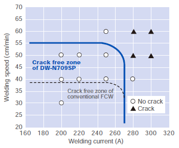
Figure 5: FISCO crack test results of PREMIARCTM
DWN709SP weld metal, showing superior hot crack
resistance over conventional FCW.
| Properties | Measurements |
|---|---|
| Tensile strength at room temp.*1 | 738 MPa (Fractured at weld metal) |
| Impact toughness at −196°C | 88, 91, 89 (Av. 88) (J) |
| CTOD at −196°C (δM) | 0.39, 0.39, 0.38 (Av. 0.38) |
| Longitudinal bending, 180° | Good |
| *1: Base metal is ASTM A553 Type I, 28mm thick, double-V groove. | |
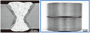
Figure 4: PREMIARCTM DW-N709SP exhibits complete
fusion in 3G-position butt joint and excellent ductility in bend
test.
TIG welding wire for 9% Ni steel
| Properties *1 | Classifications | Trade designation | |
|---|---|---|---|
| AWS A5.14 ERNiMo-8 |
JIS Z 3332 YGT9Ni-2 |
TG-S709S | |
| Features | - | - | ▪ Hastelloy type wire and rod. ▪ Suitable for automatic GTAW |
| Ship class appro. | - | - | NK |
| C (%) | ≤ 0.10 | ≤ 0.10 | 0.02 |
| Si (%) | ≤ 0.75 | ≤ 0.75 | 0.03 |
| Mn (%) | ≤ 1.5 | ≤ 3.0 | 0.03 |
| Ni (%) | ≥ 60.0 | ≥ 60.0 | 70.4 |
| Cr (%) | 0.5-3.5 | - | 2.0 |
| Mo (%) | 17.0-20.0 | 15.0-22.0 | 19.0 |
| W (%) | 2.0-4.0 | 1.5-5.0 | 3.0 |
| Fe (%) | ≤ 10.0 | ≤ 12.0 | 5.5 |
| 0.2%PS (MPa) | - | ≥ 360 | 460 |
| TS (MPa) | - | ≥ 660 | 730 |
| El (%) | - | ≥ 25 | 47 |
| IV (J) at −196°C | - | Av ≥ 34, Each ≥ 27 |
160 |
| *1: Chemical compositions are for wire. Mechanical properties are for deposited metal. |
|||
Ever since Kobe Steel’s MC-TIL process for automatic TIG welding was developed in 1973, it has been applied widely by tank fabricators, particularly in Japan. Overseas, it has been adopted in more than 10 units of LNG tanks made of 9% Ni steel and in about 60 units in the Japanese domestic market.
This efficient automatic TIG welding involves the application of a large welding current and the intentional deflection of arc direction by magnetic force, and it is able to maintain the soundness of weld metal, the principle advantage of GTAW. It is two times more efficient than SMAW and four times more than manual GTAW. Furthermore, the process reduced the defect ratio to almost zero and improved the completion time, total cost and quality of the weld.
AWS and JIS specifications for TIG wires for 9% Ni steel and the properties of the matching filler wire PREMIARCTM TG-S709S are shown in Table 8.
SAW wires and fluxes for 9% Ni steel
| Classification | AWS A5.14 | JIS Z 3333 | |
|---|---|---|---|
| ERNiMo-8 | FS9Ni-F/YS9Ni | FS9Ni-H/YS9Ni | |
| Applicable to | wire | Weld metal | Weld metal |
| C (%) | ≤ 0.10 | ≤ 0.10 | ≤ 0.10 |
| Si (%) | ≤ 0.75 | ≤ 1.5 | ≤ 1.5 |
| Mn (%) | ≤ 1.5 | ≤ 3.5 | ≤ 3.5 |
| Ni (%) | ≥ 60.0 | ≥ 60.0 | ≥ 60.0 |
| Cr (%) | 0.5-3.5 | - | - |
| Mo (%) | 17.0-20.0 | 10.0-25.0 | 10.0-25.0 |
| W (%) | 2.0-4.0 | - | - |
| Fe (%) | ≤ 10.0 | ≤ 20.0 | ≤ 20.0 |
| 0.2%PS (MPa) | - | ≥ 365 | ≥ 365 |
| TS (Mpa) | - | ≥ 660 | ≥ 660 |
| El (%) | - | ≥ 25 | ≥ 25 |
| IV (J) at −196°C | - | Av. ≥ 34 Each ≥ 27 |
Av. ≥ 34 Each ≥ 27 |
In its SAW specifications, the AWS regulates wires only in A5.14 whereas JIS specifies the combination of wire and flux, as shown in Table 3 and Table 9. Kobe Steel’s SAW wire and flux combinations are shown in Table 10.
| Trade desig. (Flux/wire) |
Classification | Features | Pol. | Ship class appro. |
Chemical composition (%) | Mechanical properties | |||||||||||
|---|---|---|---|---|---|---|---|---|---|---|---|---|---|---|---|---|---|
| AWS A5.14 |
JIS Z 3333 |
C | Si | Mn | Ni | Cr | Mo | W | Fe | 0.2%PS (MPa) |
TS (MPa) |
El (%) |
IV (J) at −196°C |
||||
| PF-N3/ US-709S |
ER NiMo-8 (wire) |
FS9Ni- F/YS9Nil |
▪ Hastelloy type consumables ▪ Suitable for 1G welding position |
AC, DCEP |
- | 0.03 | 0.12 | 1.70 | 64.1 | 1.6 | 16.6 | 2.5 | 14.7 | 400 | 690 | 44 | 80 |
| PF-N4/ US-709S |
ER NiMo-8 (wire) |
FS9Ni- F/YS9Nil |
▪ Hastelloy type consumables ▪ Suitable for 2G welding position |
DCEP | NK | 0.03 | 0.74 | 0.58 | 64.0 | 1.7 | 17.2 | 2.7 | 14.9 | 410 | 680 | 43 | 70 |
Welding procedures and control
The key factor for the economical and qualitative tank construction is to minimize the amount of on-site fabrication work. This can be achieved by adopting modular design, in which each module is fabricated at a plant and delivered to the site for the connection work afterwards. Even the dome ceiling of an LNG tank is fabricated at a plant and connected to the shell onsite by using the airraising process.
The welding joints that are typically carried out on 9% Ni steel components on-site is shown in Figure 6. Table 11 shows the welding procedures used on individual joints.
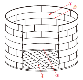
Figure 6: Cross sectional view of typical welding joints in the
shell and bottom of a 9% Ni steel tank in on-site fabrication.
(Refer to Table 11 for individual welding procedures)
| Joint No. | ① | ② | ③ | ④ |
|---|---|---|---|---|
| Component | Side shell | Side shell | Bottom to side shell |
Bottom |
| Type of joint | Double V | Double V | Double bevel | Lap |
| Welding position*1 |
3G | 2G | 2G | 2F |
| Welding process*2 |
SMAW FCAW Auto-TIG |
SAW Auto-TIG |
SAW Auto-TIG |
SMAW FCAW Auto-TIG |
| *1: 3G (Vertical groove); 2G (Horizontal groove); 2F (Horizontal fillet). *2: Kobelco auto-TIG welding equipment is available only in Japan. |
||||
[Note: Inconel is a trademark of Special Metals Corp.
Hastelloy is a trademark of Haynes International.]
Figure 7 shows examples of groove configurations for SMAW, GTAW, SAW and FCAW in designated welding positions in the figure. Figure 8 shows horizontal fillet welding (2F) on the roof of an LNG tank with DW-N709SP flux cored wire. Figure 9 shows overhead butt joint welding (4G) along the bottom plate of an LNG tank with automatic TIG welding equipment using TG-S709S TIG wire. These pictures were taken at a construction site in Japan where the major aboveground LNG tanks use the flat-bottom double-shell cylindrical dome-roof structure (Figure 10). The dome roof is also made of 9% Ni steel.
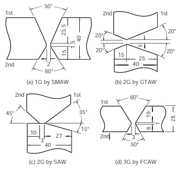
Figure 7: Typical groove configurations for SMAW, GTAW,
SAW, and FCAW used for joining 9% Ni steel components
in fabrication of an LNG tank.
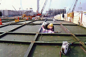
Figure 8: Horizontal fillet welding (2F) on the roof of an LNG
tank is carried out with PREMIARCTM DW-N709SP flux
cored wire.
![Figure 10: Cross sectional view of the flat-bottom doubleshell cylindrical dome-roof LNG tank [3].](../../images/education-center/technical_hightlight/vol02_10.jpg)
Figure 10: Cross sectional view of the flat-bottom doubleshell
cylindrical dome-roof LNG tank [3].
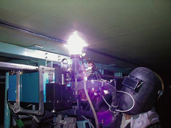
Figure 9: Overhead butt joint welding (4G) along the bottom
plate of an LNG tank is conducted with automatic TIG
welding equipment using PREMIARCTM TG-S709S TIG wire.
Tips for better welding results on 9% Ni steel
High Ni alloy welding consumables are hot crack sensitive in general, and LNG tanks typically require much dissimilar welding. The following special precautions against hot crack and base metal dilution have to be taken.
Crater crack must be removed: Kobe Steel’s welding consumables for 9% Ni steel have been proven to be adequate through the inspection by FISCO crack testing for hot crack susceptibility. However, because crater cracks (one type of hot crack) are common and difficult to avoid, it is strongly recommended for the crater to be ground off each time when the arc stops.
Dilution of base metal affects the mechanical properties of the weld metal: When the base metal is diluted into the weld metal by the arc, the weld metal chemistries can change. These changes can be especially more significant in dissimilar welding, decreasing the tensile strength of the weld metal. It is advised to check the welding conditions and to ensure that the tensile strength and 0.2% proof strength fulfill the requirements in the procedure test in advance.
[1] JOGMEC (Japan Oil, Gas and Metals National Corporation), LNG Market and Demand, 2010.
[2] Ishikawajima-Harima Engineering Review, Vol. 50, No. 1 (2010).
[3] Ishikawajima-Harima Heavy Industries, LNG Tank ― Its Structure, Materials and Welding Techniques, Iron & Steel, (1978) No. 1.
[4] Kobe Steel, Welding Technical Report, (1996) No. 312
[5] Kobe Steel, Welding Procedure Textbook, Welding of LPG and LNG Storage Tanks.
Products
- Main Products
- Welding Consumables
- Arc welding robots
- Industries - Recommended Materials
- Welding Handbook Quick View
- Product Quick View & Highlights
- For HEAT-RESISTANT STEEL
- For STAINLESS STEEL
- For LOW-TEMPERATURE STEEL
- Product Highlight
- Catalog
- Technical Highlights
- Certification
- SDS ※English Only
- ARCMAN
- Welding Robot
- Software


