

- Home >
- Products >
- Technical Highlight >
- Vol.5: Unrivaled Kobelco Filler Metals Match New Developments in Hydropower Penstocks >
Technical Highlight Vol.5
Unrivaled Kobelco Filler Metals Match New Developments in Hydropower Penstocks
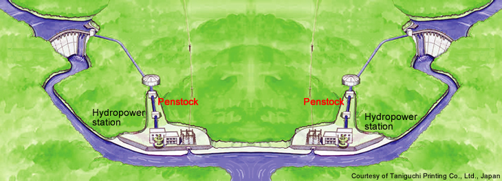
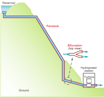
Figure 1: A cutaway view of hydropower penstock.
A penstock is a steel pipe or conduit used to carry water to a water wheel or turbine. The penstock takes water from the water gate of a reservoir and carries it to the hydropower generator that is installed in a hydropower station (Figure 1). Hydropower stations have seen increases in capacity to meet growing demand for electricity. Consequently, the steels used for penstocks have been required to have higher tensile strengths and thicker walls to withstand higher water pressures. This article discusses high tensile strength steels and filler metals used for the welding of penstocks.
Larger and stronger penstocks
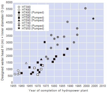
Figure 2: Transition of the scale of penstock in Japan.
Penstock scale is generally determined by the product of the water head and the inner diameter ([H] x [D]) for which the penstock is designed. As shown in Figure 2, the scale of penstocks in Japan has continually increased since 1955 as a result of the scalingup of pumped storage hydropower stations. Accordingly, the tensile strength of steels used in penstocks has increased to reduce construction terms and costs. Whereas 780 MPa class (HT780) high tensile strength steel was used extensively in many penstocks in Japan in the 1970s, by 2001, high tensile strength steel of the 950 MPa class (HT950) was adopted in the construction of Tokyo Electric Power’s Kannagawa Power Station in Japan.
In addition to the HT780 and HT950 steels mentioned above, high tensile strength steels of the 490 and 570 MPa classes (HT490 and HT570) are used where water pressure is lower or in the upper part of a penstock. The requirements of the Japanese Industrial Standard (JIS) for the chemical and mechanical properties of HT490, HT570 and HT780 steel plates are shown in Table 1. HT950 steel is specified by The Japan Electrotechnical Standards and Codes Committee (JESC) as in JESC H0001: Technical Guide for Applications of 950 MPa Class High Tensile Strength Steels in Penstocks, which is enacted by The Japan Hydraulic Gate and Penstock Association. The typical chemical composition and mechanical properties of and the requirements for HT950 steel plate are shown in Table 2.
| Class | HT490 | HT570 | HT780 |
|---|---|---|---|
| JIS | G3106 | G3128 | |
| Grade | SM490B | SM570 | SHY685NS |
| Thick. (mm) | t ≤ 200 | t ≤ 100 | t ≤ 100 |
| C% max. | 0.18-0.20 as per t |
0.18 | 0.14 |
| Si% max. | 0.55 | 0.55 | 0.55 |
| Mn% max. | 1.65 | 1.70 | 1.50 |
| P% max. | 0.035 | 0.035 | 0.015 |
| S% max. | 0.035 | 0.035 | 0.015 |
| Ni% | - | - | 0.30-1.50 |
| Others % max. |
- | - | Cu:0.50, Cr:0.80, Mo:0.60, V:0.05, B: 0.005 |
| Ceq*1 % max. | - | 0.44-0.47 as per t (QT) |
0.53-0.57 as per t*2 |
| YS, min. (MPa) |
275-325 as per t |
420-460 as per t |
665-685 as per t |
| TS (MPa) | 490-610 | 570-720 | 780-930, 760-910 as per t |
| IV, av. min. (J) | 27 at 0°C | 47 at –5°C | 47 (each 27) at –40°C |
| *1: Ceq = C + Mn/6 + Si/24 + Ni/40 + Cr/5 + Mo/4 + V/14 *2: Supplier and purchaser shall agree for 75 < t ≤ 100 mm. |
|||
| Typical [Ref. 3] | Requirement | ||
|---|---|---|---|
| Thick. (mm) |
50 | ≤ 50 | 50 < t ≤ 75 |
| C% | 0.10 | 0.14 max. | 0.14 max. |
| Si% | 0.25 | - | - |
| Mn% | 0.92 | - | - |
| P% | 0.003 | 0.010 max. | 0.010 max. |
| S% | 0.004 | 0.005 max. | 0.005 max. |
| Cu% | 0.17 | - | - |
| Cr% | 0.53 | - | - |
| Ni% | 1.39 | - | - |
| Mo% | 0.48 | - | - |
| V% | 0.040 | - | - |
| B% | 0.0011 | - | - |
| Ceq | 0.52 | 0.59 max. | 0.62 max. |
| Pcm *1 | 0.25 | 0.29 max. | 0.33 max. |
| YS (MPa) | 994 | 885 min. | 885 min. |
| TS (MPa) | 1,033 | 950-1130 | 950-1130 |
| IV (J) | 219 at –50°C | 47 min. at –55°C | 47 min. at –60°C |
| *1: Pcm=C+Si/30+Mn/20+Cu/20+Ni/60+Cr/20+Mo/15+V/10+5B | |||
Filler metals for HT490, HT570 and HT780 steels
High strength filler metals for SMAW, FCAW, GMAW, GTAW, and SAW are available from Kobe Steel, as shown in Tables 3 through 5 for the respective tensile strength level of 490, 570 and 780 MPa.
| Process | SMAW | FCAW | GMAW | SAW | ||
|---|---|---|---|---|---|---|
| Trade desig. |
LB-52 | LB-52A | DW-100 | MG-S50 | MF-38/ US-36 |
PF- H55AS/ US-36J |
| AWS | A5.1 E7016 |
A5.1 E7016 |
A5.20 E71T- 1C |
A5.18 ER70S- G |
A5.17 F7A6- EH14 |
A5.17 F7A8- EH14 |
| Polarity | AC*1, DCEP |
AC*1, DCEP |
DCEP | DCEP | AC | DCEP |
| C% | 0.08 | 0.08 | 0.05 | 0.08 | 0.09 | 0.07 |
| Si% | 0.60 | 0.57 | 0.45 | 0.62 | 0.23 | 0.23 |
| Mn% | 0.94 | 1.12 | 1.35 | 1.12 | 1.62 | 1.42 |
| P% | 0.011 | 0.012 | 0.013 | 0.010 | 0.014 | 0.009 |
| S% | 0.006 | 0.005 | 0.009 | 0.008 | 0.007 | 0.004 |
| Ti% | - | - | - | - | - | 0.021 |
| B% | - | - | - | - | - | 0.004 |
| YS (MPa) | 500 | 500 | 510 | 450 | 470 | 485 |
| TS (MPa) | 570 | 580 | 570 | 570 | 570 | 555 |
| El (%) | 32 | 31 | 30 | 28 | 30 | 33 |
| IV, av. (J) | 210 at 0°C |
230 at 0°C |
110 at 0°C |
180 at –20°C |
125 at 0°C |
180 at –45°C |
| *1: Chemical and mechanical properties given here are for AC. | ||||||
| Process | SMAW | GMAW | Auto GTAW |
SAW | ||
|---|---|---|---|---|---|---|
| Trade desig. |
LB-62UL | MG-S63B | TG-S60A | MF-38/ US-49 |
PF-H80AK/ US-56B |
|
| AWS | A5.5 E9016-G |
A5.28 ER90S-G |
A5.28 ER80S-G |
A5.23 F8A4- EG-A4 |
A5.23 F9A6- EG-G |
|
| Polarity | AC, DCEP*1 |
DCEP | DCEP | AC | AC, DCEP*1 |
|
| C% | 0.05 | 0.08 | 0.06 | 0.07 | 0.06 | |
| Si% | 0.59 | 0.50 | 0.04 | 0.27 | 0.36 | |
| Mn% | 1.20 | 1.09 | 1.23 | 1.35 | 1.36 | |
| P% | 0.009 | 0.007 | 0.007 | 0.015 | 0.010 | |
| S% | 0.005 | 0.008 | 0.009 | 0.010 | 0.006 | |
| Ni% | 0.59 | - | 0.92 | - | 0.81 | |
| Cr% | - | 0.42 | - | - | - | |
| Mo% | 0.26 | 0.29 | 0.62 | 0.42 | 0.45 | |
| YS (MPa) | 551 | 601 | 590 | 530 | 611 | |
| TS (MPa) | 645 | 662 | 670 | 630 | 668 | |
| El (%) | 28 | 28 | 27 | 25 | 25 | |
| IV, av. (J) | 188 at –20°C |
161 at –20°C |
270 at –60°C |
97 at –5°C |
123 at –40°C |
|
| *1: Chemical and mechanical properties given here are for DCEP. | ||||||
| Process | SMAW | GMAW | Auto GTAW |
SAW | ||
|---|---|---|---|---|---|---|
| Trade desig. |
LB-80UL | LB-80L | MG-S80 | TG- S80AM |
PF- H80AK/ US-80LT |
PF- H80AS/ US-80LT |
| AWS | A5.5 E11016- G |
A5.5 E11018- G H4 |
A5.28 E110S- G |
A5.28 E110S -G |
A5.23 F12A10- EG-G |
A5.23 F11A10- EG-G |
| Polarity | AC | DCEP | DCEP | DCEP | AC | DCEP |
| C% | 0.08 | 0.04 | 0.06 | 0.08 | 0.08 | 0.07 |
| Si% | 0.52 | 0.60 | 0.40 | 0.09 | 0.28 | 0.44 |
| Mn% | 1.50 | 1.39 | 1.15 | 1.12 | 1.65 | 1.60 |
| P% | 0.009 | 0.009 | 0.010 | 0.006 | 0.009 | 0.011 |
| S% | 0.006 | 0.006 | 0.001 | 0.003 | 0.004 | 0.004 |
| Ni% | 1.90 | 2.88 | 2.67 | 2.85 | 2.45 | 2.43 |
| Cr% | 0.28 | - | 0.19 | 0.36 | 0.07 | 0.08 |
| Mo | 0.43 | 0.70 | 0.51 | 0.68 | 0.74 | 0.73 |
| YS (MPa) |
710 | 770 | 764 | 760 | 836 | 773 |
| TS (MPa) |
820 | 830 | 827 | 880 | 908 | 871 |
| El (%) | 25 | 24 | 22 | 23 | 20 | 21 |
| IV, av. (J) |
99 at –20°C |
100 at –60°C |
109 at –20°C |
240 at –60°C |
103 at –60°C |
79 at –60°C |
Strong and tough fi ller metals for HT950 steel
| Base metal thick. (mm) | t ≤ 100 | 100 < t ≤ 200 |
|---|---|---|
| Joint tensile strength (MPa) | 950 min. | 930 min. |
| Transition temp., vTrs (°C) | –10 or lower | –15 or lower |
| Absorbed energy, min. vE (J) | 47 at –10°C | 47 at –15°C |
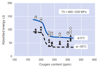
Figure 3: Effect of oxygen content in SMAW weld metal of HT950 on Charpy impact absorbed energy.
| Filler metal and process |
Covered electrode for SMAW |
Solid wire for GMAW*2 |
Solid wire for auto GTAW |
Flux and wire for SAW |
||
|---|---|---|---|---|---|---|
| C% | 0.05 | 0.06 | 0.06 | 0.09 | ||
| Si% | 0.39 | 0.34 | 0.30 | 0.53 | ||
| Mn% | 1.35 | 1.34 | 1.43 | 1.79 | ||
| P% | 0.004 | 0.005 | 0.004 | 0.011 | ||
| S% | 0.003 | 0.003 | 0.006 | 0.002 | ||
| Ni% | 3.37 | 2.60 | 3.18 | 2.60 | ||
| Cr% | 0.58 | 0.46 | 0.81 | 0.07 | ||
| Mo% | 0.46 | 0.75 | 0.96 | 0.75 | ||
| O% | 0.016 | 0.016 | 0.001 | 0.019 | ||
| TS(MPa) | 965 | 960 | 1019 | 1002 | 959 | 962 |
| IV, av. (J) at –20°C |
137 | 138 | 111 | 224 | 120 | 152 |
| vTrs (°C) | < –60 | < –60 | < –60 | < –60 | < –60 | < –60 |
| CTOD, δm*3 (mm) at 0°C |
0.26 0.27 |
0.22 0.23 |
0.17 0.18 |
0.66 0.64 |
0.26 0.25 |
0.27 0.26 |
| Welding position |
Flat | Verti- cal |
Flat | Flat | Flat | Flat |
| Heat input (kJ/mm) |
2.5 | 3.5 | 1.3 | 5.0 | 3.3 | 4.5 |
| *1: Tensile strengths are those of butt weld joints for SMAW and SAW; the other properties are those of weld metals. *2: 95%Ar-5%CO2 shielding gas was used. *3: Tested as per WES 1108-1995, with B=W=50 mm specimen. |
||||||
HT950 steel penstocks are constructed in accordance with the Technical Guide JESC H0001, which requires the following to prevent penstock fracture in operation at a minimal service temperature of 0°C: (1) a base metal to arrest propagation of a brittle crack; and (2) welds (weld metal and base-metal heat-affected zone) that will not initiate a brittle fracture. Since it is inherently difficult for a weld to secure an equivalent level of toughness as the base metal, the Technical Guide aims primarily to have brittle cracks arrested by the base metal.
The mechanical properties required by the Technical Guide for welds are shown in Table 6. The tensile strength given in the table is the minimum tensile strength of a plate-type transversal test specimen removed across a butt weld joint (as per JIS Z 3121-1993) but not of an all-weld metal specimen. Thus, the weld metal can be lower in tensile strength than the base metal. Known as an undermatching weld joint, it is designed to minimize the cold crack susceptibility of the weld while keeping the joint strong enough to sustain the tensile stress that may arise during operation.
When tensile strength increases, the impact toughness of high tensile strength weld metals tends to decrease. To address this issue, Kobe Steel has developed tough filler metals for HT950 steel by reducing oxygen in the weld metal (Figure 3) to refine the microstructure and improve the resistance to ductile cracking, by adding nickel in the weld metal to toughen the matrix of the microstructure, and by adjusting the chemistry of the weld metal to create a fine acicular ferrite structure.
As the tensile strength of weld metal increases, the weld metal also becomes more susceptible to diffusible hydrogen, which may cause cold cracking. To improve crack resistance, Kobe Steel has devised how to reduce the source of hydrogen in filler metals that maintain good welding usability. For the SMAW electrode covering and the SAW flux, the production process was innovated and the raw material composition was elaborated to decrease the water content and the hydrogen partial pressure in the arc atmosphere. For GMAW and GTAW wires, the lubricant has been improved.
These advances have enabled Kobe Steel to develop the exceptional filler metals for HT950 steel penstocks. Table 7 shows the chemical and mechanical properties of the Kobelco filler metals. With these HT950 filler metals, the welding procedure can be comparable to that for conventional HT780 filler metals. With the unsurpassed properties shown in the table, these filler metals have successfully been applied in the construction of penstocks for two hydropower stations in Japan.
High-tech welding procedures are required in the construction of penstocks
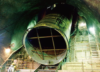
Figure 4: A unit pipe is joined to another unit pipe one by one in the inclined tunnel to construct the penstock (Courtesy of Mitsubishi Heavy Industries, Ltd., Japan).
In many cases, a hydropower penstock is fabricated first at a workshop that is temporarily built near the penstock construction site. At the workshop, two or three rolled sections of steel are seam welded mainly by SAW to fabricate a single pipe with a length of about 3 meters. Next, three or four single pipes are butt-joined mainly by SAW to produce a unit pipe of 9-12 meters long. The unit pipes are delivered to the site — many cases into the inclined tunnel — where the penstock is to be installed. Then the unit pipes are joined by SMAW, automatic GMAW, or automatic GTAW to construct the penstock. Figure 4 shows a unit pipe being delivered into the inclined tunnel. Figure 5 shows the automatic one-sided GMAW process setup inside the unit pipe to butt weld two unit pipes.
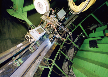
Figure 5: An automatic one-sided GMAW process
setup on
the butt joint of two unit pipes inside the inclined tunnel
(Courtesy of Mitsubishi Heavy Industries, Ltd., Japan).
As shown in Figure 1, when a single penstock feeds several hydropower generators with pressurized water, the penstock branches to separate the water. When the penstock separates the water into two lines, penstock branching is more commonly referred to as bifurcation. Figure 6 illustrates how bifurcation is typically carried out at a fabrication plant. Generally a penstock is bifurcated at its lowest part where the water pressure is highest. To bear the burden of high water pressure, the bifurcation will be a heavy-duty structure composed of HT780 or HT950 steel pipes with heavy-thick stiffeners.
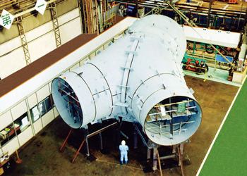
Figure 6: A penstock bifurcation under production at a fabrication plant (Courtesy of Mitsubishi Heavy Industries, Ltd., Japan).
In the underground tunnel, the unit pipes are placed in ambient air of around 15°C and of almost saturated humidity. During welding, the joints have to be maintained at the required preheating and interpass temperatures (e.g. 100-125°C or higher for 50 or thicker HT780 steel pipe) to prevent cold cracking in the weld. Therefore, the welding operation has to be carried out in a high-temperature high-humidity atmosphere.
Manual welding under these high-temp/high-humidity conditions is harsh on welders. Tunnel diameter must also be wide enough to secure a large enough working space. To address the human safety and the economic issues, the welding process has been automated by employing one-sided automatic GMAW and GTAW processes.
Because high humidity (a source of water, and thus hydrogen) can promote cold cracking and delayed cracking in the weld, controlling preheat and interpass temperatures, postweld heating, and keeping filler metal dry are essential to prevent these effects. In addition, heat input must be controlled to ensure sufficient tensile strength and notch toughness of the weld. The exact requirements for these procedure control parameters depend on the type of steel, plate thickness, and type of filler metal.
References:
[1] Quarterly Journal of the Japan Welding Society, Vol. 21 (2003) No 1.
[2] Journal of the Japan Welding Society, Vol. 78 (2009) No 6.
[3] Hitachi Shipbuilding Engineering Reports, Vol. 58 (1998) No. 4.
[4] Kobe Steel, Welding technical guide, (1997) No. 331.
Products
- Main Products
- Welding Consumables
- Arc welding robots
- Industries - Recommended Materials
- Welding Handbook Quick View
- Product Quick View & Highlights
- For HEAT-RESISTANT STEEL
- For STAINLESS STEEL
- For LOW-TEMPERATURE STEEL
- Product Highlight
- Catalog
- Technical Highlights
- Certification
- SDS ※English Only
- ARCMAN
- Welding Robot
- Software


