

- Home >
- Products >
- Technical Highlight >
- Vol.8: Typical Applications of ARCMAN™ Robot Welding Systems for Construction Machinery >
Technical Highlight Vol.8
Typical Applications of ARCMAN™ Robot Welding Systems for Construction Machinery
Introduction
An article in the preceding issue briefly introduced Kobelco’s welding system business and described the ARCMAN™ series arc welding robots and the SENSARC™ series arc welding power sources, which configure the welding robot system, focusing on the latest models and their features. The popular ARCMAN™ series robots are used mainly by customers in the medium/thick plate welding fields such as construction machinery, steel frame buildings, bridges, and railroad cars. The present issue will focus on how the ARCMAN™ series have typically been employed by the construction machinery fabricators.
The need for welding robots in the fabrication of construction machinery
In the field of medium/thick plate welding, the use of welding robots has progressed farthest in construction machinery fabrication. The main reason for this can be attributed to the low-mix, high-volume production in the fabrication of construction machinery compared to other fields. Additionally, the consumption ratio of the welding consumables needed for the fabrication of construction machinery is as high as about 1% by weight. That is, a 20-MT class hydraulic excavator (Figure 1), which is produced at the highest volume, requires about 200kg of welding consumables per one unit. Because of the large consumption of welding consumables as well as the need for consistent weld quality, welding robots, which have two to three times the capability of human welders, have steadily gained favor in the construction machinery field.
Requirements for the welding of construction machinery
The workpieces for construction machinery have a number of particular characteristics; hence, the welding robot must be able to work within a particular set of constraints, as follows:
(1) The complex shapes of the workpieces require groove welding and multi-layer welding.
(2) Flat welding is often used to obtain high welding efficiency, better penetration, and smoother bead appearance. Therefore the workpiece must be fixed on a positioner to place it at the most suitable position for flat welding.
(3) Large workpieces require many hours of production to complete, and welding accounts for significant amounts of the production time. To reduce time spent on welding, processes offering high deposition rates, such as tandem arc welding, are favored.
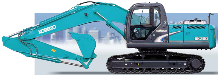
Figure 1: A20-MT class hydraulic excavator needs about 200kg of welding consumables to fabricate.
Employing robotic welding for the “arm” component of a hydraulic excavator
The welding of hydraulic excavator arms provides a good example of how the ARCMAN™-MP, Kobelco’s best-selling model, is applied in construction machinery fabrication. By employing this welding system, the welding cycle time can be shortened, and the weld quality can be improved. Following are the characteristics of this system.
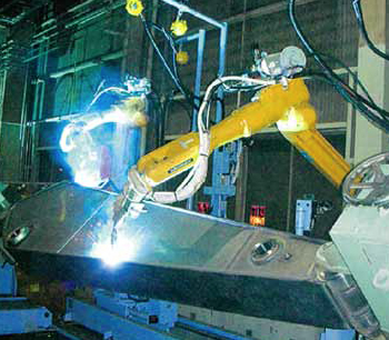
Figure 2: The twin-robot system reduces production time due to simultaneous operations.
Twin robots
With this system, two robots weld one workpiece at the same time as shown in Figure 2, thereby shortening the production hours. In order to maximize the effect of twin-robot welding, each robot is responsible for welding the predetermined portions of the workpiece so that they will finish in roughly equal amounts of time.
Groove-width tracking function
Using an arc sensor to measure the groove width during welding, this function sequentially corrects welding speed and weaving conditions according to the measured groove width. With this function, welds can be produced with uniform bead height and sufficient penetration, even on workpieces with varied groove widths.
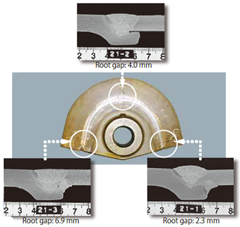
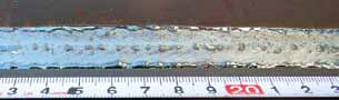
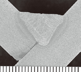
Figure 3: Part of an arm component exhibits uniform weld
appearance (middle) and three cross-sectional
macrostructures (top & bottom) show sufficient penetration.
Figure 3 shows the test results of welds produced with the groove-width tracking and multi-layer welding functions. The groove shape was 50°V. The groove width was varied by changing the root gap before welding along the weld axis: 2.3 mm at the start, 4 mm at the middle, and 6.9 mm at the end. Welding was completed with three layers. The final layer welding was carried out according to the sequential mode set by the original teaching, regardless of the subsequent groove width measurements.
Consequently, the tests show that, on workpieces with varied groove widths, multiple layer welds can be obtained with sufficient penetration and virtually uniform height of reinforcement. It is noteworthy that the final layer of the welds exhibited regular bead width regardless of fluctuation in groove width.
Switching function for the welding and tool parameters
Most welding lines of a workpiece can be welded with the standard wire extension and gas shielding. However, for a deep single-bevel groove joint around a boss part, the wire extension must be switched to become longer in order to avoid torch-to-workpiece interference, thereby expanding the application range for the robot welding of the workpiece.
Using a tandem welding system for hydraulic excavator “booms”
A tandem welding system can reduce welding cycle time and minimize the number of systems to be installed; such benefits lead many fabricators in the construction machinery field to employ such systems.
Introduced here is an example of Kobelco’s tandem welding system that is combined with ARCMAN™ -SR, a compact welding robot that can easily be set up overhead to maximize the capabilities of robot welding. In this system, the slider and positioner are integrated, reducing the system’s footprint, and the positioner is equipped with an up-down axis, which improves operability when setting a workpiece. Figure 4 shows this system in operation.
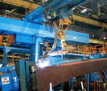
Figure 4: ARCMAN™-SR (suspended overhead) in operation on the boom in the tilted position.
Higher efficiency by tandem welding
Using the rotating/tilting positioner, the tandem system allows all joints to be welded in the flat position, which maximizes efficiency and provides good penetration and bead appearance. Tandem arc welding can reduce the welding time of conventional single arc welding by 30-50%. This tandem arc welding system is able to obtain both increased welding speeds and sound weld beads due to its two-electrode, one-pool welding technique. Figure 5 shows bead appearance and cross-sectional macrostructure by single and tandem arc welding in the typical welding conditions for flat fillet welds with a leg length of 9 mm. As shown in the figure, tandem arc welding speed can be nearly 2 times (1.75 times) faster than conventional single arc welding.
| Welding conditions | Bead appearance | Cross-sectional macrostructure |
|
|---|---|---|---|
| Single welding |
▪ Amperage: 380A ▪ Carriage speed: 40 cm/min |
 |
 |
| Tandem welding |
▪ Amperage: Leading: 340A Trailing: 320A ▪ Carriage speed: 70 cm/min |
 |
 |
Ultra-low spatter in tandem welding
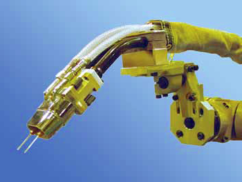
Figure 6: Compact integrated tandem torch offers easier access in a confined space and prevents the welding cable from getting tangled around the wrist of the robot.
To improve arc stability and reduce spatter generation, pulsed welding is applied, in which the peak and base currents are synchronized between the leading and trailing wires by the special welding output control. With this output control, the new system can reduce spatter generation by an impressive 70% and even produces smaller spatter particles than conventional systems.
Wider applications with compact integrated tandem torch
As shown in Figure 6, this system uses a compact integrated tandem torch, which can easily access the welding lines in the confined area of a workpiece and prevents the torch cables from getting tangled around the wrist of the robot. This integrated tandem torch therefore allows the robot to tackle a wide range of applications than robots equipped with a conventional tandem torch.
Improved weld quality with the Dual-arc sensing function (trailing-wire tracking)
In order to obtain high quality welds in tandem arc welding, the leading and trailing wires must accurately track the welding line. If one of the two wires deviates from the welding line, the weld may contain such defects as undercut and insufficient penetration.
Even when the teaching is conducted accurately on a medium/thick plate workpiece, the welding wires may deviate from the welding line due to workpiece processing errors, thermal distortion, or the curvature of the welding wire.
Arc sensing is one way to overcome this problem. However, conventional arc sensors are effective only when the amounts of deviation of both the leading and trailing wires from the welding line are almost the same. In production, however, the failure to input accurately the tracking line of the trailing wire in the memory during the teaching operation or a curvature in the trailing wire may cause the leading wire and the trailing wire to deviate to different degrees. Such deviations of the trailing wire can cause weld imperfections because conventional arc sensors cannot sense the deviation of the trailing wire.
To solve this problem, Kobe Steel has developed a unique “Dual arc sensor” that can sense the trailing wire, too. Test results of the Dual-arc sensor demonstrate its excellent performance in tandem welding with the trailing wire deviating by 5 mm from the welding line. The main welding conditions were as follows:
▪ Horizontal fillet welding with 8-mm leg length
▪ Welding current: 320A for the leading wire; 270A for the trailing wire
▪ Welding speed: 72 cm/min.
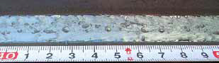
Figure 7 shows the test result obtained in tandem welding with a conventional arc sensor (without sensing the trailing arc). As shown in the figure, the deviation of the trailing wire caused a large undercut on the web plate. Also, large spatter particles can be observed on the flange plate, further undermining the weld quality.
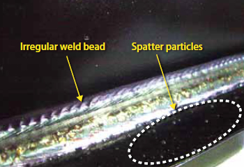
Figure 7: Weld bead appearance in tandem arc welding with
a conventional arc sensor.
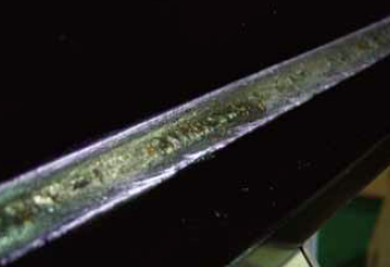
Figure 8: Weld bead appearance in tandem arc welding with a Dual-arc sensor.
In contrast, Figure 8 shows the result of a test carried out under the same conditions as above but with a Dual-arc sensor that could sense the deviation of the trailing wire and send the data to the controller to correct immediately the track of wire, thereby resulting in good weld bead appearance without defect.
The Dual-arc sensor was also tested in a case where both the leading and trailing wires deviate from the welding line (as shown in Figure 9). The results show that both the leading and trailing wires correctly tracked the welding line to produce the acceptable quality weld as shown in Table 1.
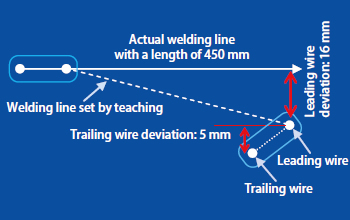
Figure 9: Deviation from actual welding line for testing the
performance of the Dual-arc sensor.
| Type of welding |
Leg length |
Welding current |
Welding speed |
Weld results |
|---|---|---|---|---|
| Flat fillet | 8 mm | Leading: 400A Trailing: 350A |
80cm/min | Good |
| Horizontal fillet | 8 mm | Leading: 350A Trailing: 300A |
75cm/min | Good |
| Flat fillet | 6 mm | Leading: 350A Trailing: 300A |
90cm/min | Good |
Postscript
As described in this article, the welding of excavator arms and booms are two common applications of robot welding systems employed in the construction machinery field. As a supplier of robot welding systems to construction machinery fabricators (among other fields), Kobe Steel’s goal is to shorten the welding cycle time and to improve weld quality by continuing to develop robots with ever-better performance and proposing the best solutions for customers.
In the next issue, we plan to introduce robotic systems used for welding medium/thick plates in other fields, such as the railroad car industry.
Kobe Steel remains engaged in helping customers improve overall manufacturing performance through the operation of Kobelco welding systems installed in their fabrication sites. Our engagement and close working relationships should lead to excellent customer satisfaction. Therefore, when robots experience repetitive short-time stoppage during operation or cause weld imperfections, which degrade the consistency of production, the causes must adequately be analyzed and the teaching operation must be improved. In the next issue we will discuss the measures taken by Kobe Steel so that we may live up to your expectations.
Products
- Main Products
- Welding Consumables
- Arc welding robots
- Industries - Recommended Materials
- Welding Handbook Quick View
- Product Quick View & Highlights
- For HEAT-RESISTANT STEEL
- For STAINLESS STEEL
- For LOW-TEMPERATURE STEEL
- Product Highlight
- Catalog
- Technical Highlights
- Certification
- SDS ※English Only
- ARCMAN
- Welding Robot
- Software


