

- Home >
- Products >
- Technical Highlight >
- Vol.9: Using ARCMAN™ Robot Welding System for Railroad Car and Bridge Applications >
Technical Highlight Vol.9
Using ARCMAN™ Robot Welding System for Railroad Car and Bridge Applications
Introduction
When used in connection with SENSARC™ series arc welding power sources, Kobelco’s ARCMAN™ series arc welding robots are well-suited for welding medium/thick steel plates. In the previous issue (Vol.15, No.2), the technical highlight article described how Kobelco’s robot welding systems are used in the construction machinery field. In this issue we focus on two more applications involving medium/thick plate welding: railroad cars and bridge construction. This article will also describe how the user-support software “AP-SUPPORT” improves production stability and efficiency.
Features of a robot welding system for railroad car construction
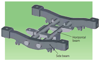
Figure 1: Chassis frame of railroad car
The railroad car is basically composed of a chassis and a body that is supported by a chassis. Quite a few ARCMAN™ robot welding systems have been supplied to railroad car manufacturers for automating the welding processes of their chassis.
Railroad cars must by nature be reliable and safe when transporting people or objects. The robotic welding processes used in constructing them must, therefore, be of high quality as well. The main components to be welded by robots are the side beam, the horizontal beam, and the chassis frame, in which both beams are connected to each other. Figure 1 shows the chassis frame.
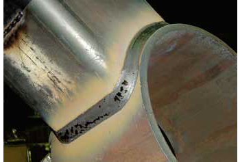
Figure 2: Chassis component with complicated welding line
Chassis components have complicated shapes such as the curved welding line with a groove as shown in Figure 2. Such complex shapes require stable deep-penetration and multi-pass welding, at which Kobelco’s robot welding systems are particularly adept. The robot’s various sensing and multi-pass welding functions are just the ticket for medium/thick plate welding.
(1) Hardware configuration of ARCMAN™ robot welding system
The standard robot welding system for welding the main components of railroad cars consists of the ARCMAN™ robot and peripheral equipment, a positioner and a slider.
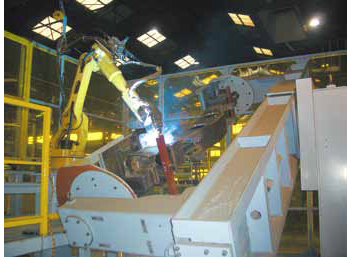
Figure 3: Robot welding system with 2-axis positioner
Figure 3 is an example of the robot welding system employing a two-axis (rotation and tilt) positioner which allows the robot to synchronously conduct flat-position welding in order to secure the highest quality.
When a 2-3 meter long workpiece is mounted for flat position welding, it has to be tilted about 70° maximum. As a result, the tilt axis center must be positioned about 1.5-2.0 meters above the floor to prevent the workpiece from touching the floor. (See Figure 4.)
Figure 4: 2-3 meter long workpiece, held 1.5-2 meters above
the floor level.
However, it can be burdensome as well as dangerous when operators are required to mount and dismount workpieces in such high positions. Therefore, Kobe Steel has provided the robot welding system with a specially-designed positioner that has an additional, up-down, axis.
(2) Efficient off-line teaching software
The teaching of the robot welding system applied to railroad car fabrication will be different for every workpiece because each one has a unique shape. The off-line teaching software, K-OTS32, is provided in order to make a more efficient teaching database for the diverse workpieces with complicated shapes.
(3) Easy plasma cutting by robot system with off-line teaching software
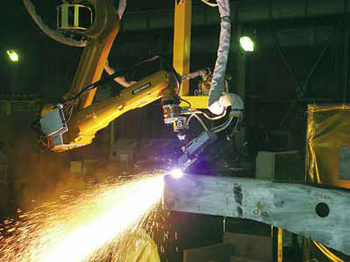
Figure 5: Plasma cutting robot system
In side beam fabrication, both the edge preparation for the welding groove and the component cutting is performed prior to welding. In general, steel material bent in a U shape is cut at the user’s factory to make the side beam component. As three dimensional (3-D) cutting is required, an articulated cutting robot is well-suited to the task. The off-line teaching system, K-OTS32, can effectively create the teaching database of the complicated movement locus.
Furthermore, because the plasma cutting machine made by Hypertherm Inc. is connected to the ARCMAN™ robot through an exclusive interface, cutting parameters such as cutting current and speed can be taught from the teaching pendant connected to the robot. As a result the operational performance is increased. Figure 5 shows an example of plasma cutting robot system.
Plasma cutting robot systems from Kobe Steel are available in two configurations. One is designed exclusively for cutting, whereas the other can carry out both cutting and welding. The latter system is mounted with both welding and cutting torches that engage automatically for their particular job. In this way, the robot achieves a high operating ratio as well as significant space-saving.
Features of robot welding systems for steel bridge construction
The GT-5000, an orthogonal NC twin welding robot for bridge construction, was released in 1988; however, these days, the ARCMAN™ series welding robots are preferred as they have special features for fabricating bridge panel components.
One improvement relates to the teaching function. Because bridge panel components have diverse designs, teaching usually has to be performed each time a new workpiece is operated on, which can mean shutting down the production line and losing productivity. In Japan, the off-line teaching can now be carried out without stopping the production line by utilizing a computer program that applies CAD data designed with a full size (see Figure 6).
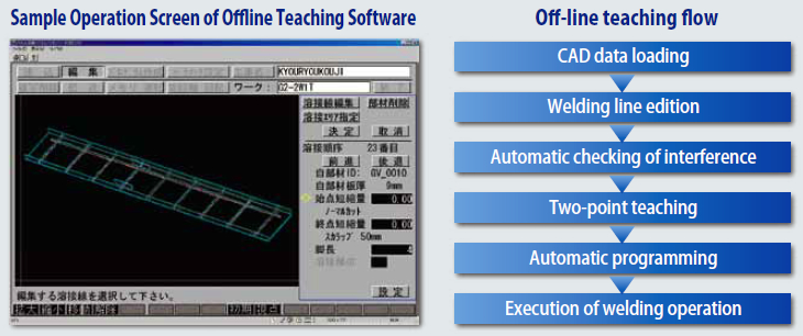
Figure 6: Off-line teaching display
(1) Major systems
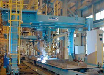
Figure 7: Gantry type twin welding system
① Twin robot welding system
One common type of system utilizes a pair of welding robots suspended overhead and set on opposite sides of the workpiece that is mounted on a slider with an extra pivot axis. Facing each other, the robots perform horizontal fillet welding on both sides of the workpiece at the same time, thereby increasing welding efficiency. Two types of twin welding systems are available: a gantry type, as shown in Figure 7, and a cantilever type, allowing the user to match the system to his needs.
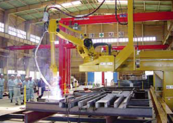
Figure 8: Compact and single robot welding system
② Single robot welding system
Compared with twin robot systems, single robot welding systems take up much less space. They can carry out welding of main girders with a width of up to 3m. The ARCMAN™-XL mk II is an extremely large robot; however, when mounted on a compact, floor-type carriage with one axis instead of a conventional overhead-suspended carriage, the size of the system is reduced and the cost is lower as well. (See Figure 8.)
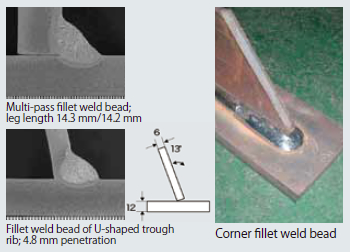
Figure 9: Multi-pass fillet weld and corner fillet weld
(2) Suitable workpieces and welding functions
Many different bridge panel members such as plate girders, box girders, U-shaped trough ribs, flange panels, and diaphragms are well-suited for robotic welding. These bridge panel members usually require corner welding and multi-pass, large leg-length welding in combination with flux cored wires.
(3) Extending monitor-less operation time
① Memory function
These welding systems feature computer memory that can be programmed to weld multiple workpieces one after the other. Continuous welding of up to 20 workpieces is possible.
② Skip function
When short-time breakdowns occur (in which an operator can quickly resolve an issue and restart the production) during automatic operation, the robot automatically conducts a series of actions. It stops welding, shifts the nozzle to its cleaning device, cleans the nozzle, returns to the position where the welding had stopped, and then re-starts welding. This function is particularly useful for monitor-less welding during night shifts.
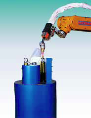
Figure 10: Automatic
nozzle-changing device
③ Automatic nozzle-cleaning and nozzle-changing devices
Spatter that sticks to a nozzle during welding may cause short-time breakdowns or welding defects due to the lack of shielding. In such cases, the nozzle can be replaced with a clean one by the automatic nozzle-changing device shown in Figure 10. The automatic nozzle - cleaning device then cleans the dirty nozzle up to the orifice located deep inside.
④ Other functions supporting continuous operation
In addition to the functions already mentioned, the computer controlling the ARCMAN™ series welding robots is programmed to prevent “wire-stick” (when the melted wire end adheres to the weld bead), nozzle-to-workpiece contact and arc-retrying. These standard functions enable the robots to be employed in continuous operation safely and effectively.
AP-SUPPORT: User support software
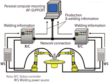
Figure 11: AP-SUPPORT network
In order for a robot welding system to maintain stable production, it is necessary to be able to monitor the system and promptly resolve any problems that occur.
AP-SUPPORT is a program that maintains production stability by allowing users to visualize the robot welding system. It was launched in October 2010. It allows users to monitor the daily operations of the ARCMAN™ robot welding system and to improve productivity. Specifically, AP-SUPPORT accurately processes production control data such as the arc generation rate as well as data generated from any problems that occur.
Figure 11 shows the AP-SUPPORT network. Quite a lot of welding information as well as production information are transferred from the robot controllers and the welding power sources through the network, into the personal computer.
With the AP-SUPPORT program, users can analyze production control data like the arc generation rate and data related to short-time breakdowns and welding defects and thereby improve productivity more efficiently.
To better understand how the program supports production and welding, it is worthwhile to look at the production monitor and arc monitor in more detail.
(1) Production monitor
The production monitor helps to control production and to improve the effects of short-time breakdowns.
One of the main functions of the production monitor is to produce a report of information related to production obtained from the robot controller. Production data obtained from the robot controller is analyzed, and the report provides details essential for production control (see Figure 12) as well as information that will allow users to improve performance in future short-time breakdowns (see Table 1). Figure 12 shows a bar chart detailing the daily arc time, non-arc time, and stoppage time due to errors or other reasons experienced daily as well as a line graph that shows the number of short-time breakdowns. This chart can help users understand whether the arc generation rate is maintained or not and how stoppage time either increases or decreases over time. Table 1 also shows teaching data (Program number and Step number) indicating the locations of the short-time breakdowns and provide error messages. From this output, users can easily recognize which part of teaching data requires modification.
Other functions of the production monitor include displaying the robot’s present status as well as the history of changed teaching data.
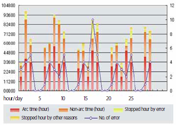
Figure 12: Output of production related information
| No. of times |
Main program |
Program no. |
Step no. |
Pass no. |
No. | Error message |
|---|---|---|---|---|---|---|
| 22 | 12 | 204 | 13 | 1 | 367 | Abnormal arc occurred (during welding) 2 |
| 15 | 13 | 302 | 13 | 3 | 693 | Abnormal arc occurred (Arc re-try) |
| 13 | 22 | 252 | 13 | 1 | 367 | Abnormal arc occurred (during welding) 2 |
| 22 | 22 | 255 | 16 | 1 | 367 | Abnormal arc occurred (during welding) 1 |
| 9 | 13 | 304 | 13 | 2 | 693 | Abnormal arc occurred (Arc re-try) |
| 8 | 11 | 127 | 12 | 0 | 452 | Movement of a certain distance is not enough to keep away from a wall (Touch-off) |
For more detailed analysis, the monitor can also report on the number of sensing actions, the number of times sensing is corrected, or waiting time due to timer setting. For example, if the output report indicates the amount of sensing corrections for the workpiece is quite small, it may be judged that the workpiece is accurate and that sensing operations can be omitted, leading to shorter takt time.
Ultimately, the production monitor’s report-output function helps users to improve productivity and automation by utilizing information obtained and analyzed by operators in the past.
(2) Arc monitor
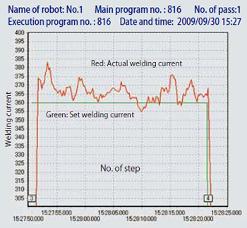
Figure 13: Output of arc monitoring
The arc monitor function helps users solve such welding problems as lack of leg length, unstable arc, and deviation of welded line. Such information related to the welding as welding current, arc voltage, welding speed, corrected amount of track-sensing, adjusted amount of arc sensing is obtained from the robot controller and displayed in the graphs on the arc monitor screen as shown in Figure 13.
Robot welding systems connected to the latest SENSARC™ AB500 power source can obtain wire feeding information (e.g. the wire feeding load) that can cause welding defects. Another function can judge the appropriateness of the set welding current against the actual welding current. The arc monitor screen displays not only present welding data in real time but also past welding data. It enables users to better investigate the causes of current welding defects as well as to trace the welding history.
Postscript
Readers of Kobelco Welding Today may have noticed that the Technical Highlight columns in 2012 have featured KOBELCO’s robot welding systems three times in a row. We hope that readers by now well understand the excellent features and benefits of our robot welding systems.
KOBELCO plans to continue to enhance the product lines, functions as well as the application software of our welding systems to enable our clients to achieve more efficient and stable production. As one of the most prominent manufacturers of welding consumables in the world, Kobe Steel takes pride in presenting total solutions that combine strengths coming from the areas of welding consumables, robot welding systems and welding power sources. KOBELCO will continue to provide our clients with the ARCMAN™ robot welding systems, by making use of these advantages and strengths.
Products
- Main Products
- Welding Consumables
- Arc welding robots
- Industries - Recommended Materials
- Welding Handbook Quick View
- Product Quick View & Highlights
- For HEAT-RESISTANT STEEL
- For STAINLESS STEEL
- For LOW-TEMPERATURE STEEL
- Product Highlight
- Catalog
- Technical Highlights
- Certification
- SDS ※English Only
- ARCMAN
- Welding Robot
- Software


