

- Home >
- Products >
- Technical Highlight >
- Vol.11: STATE-OF-THE-ART AUTOMATIC ARC WELDING PROCESSES MEET THE LATEST SHIPBUILDING REQUIREMENTS >
Technical Highlight Vol.11
STATE-OF-THE-ART AUTOMATIC ARC WELDING PROCESSES MEET THE LATEST SHIPBUILDING REQUIREMENTS
A wide variety of cargo ships ply the world's seas and oceans in great numbers. These bulk carriers, oil tankers, and container ships must be strong enough to travel safely through typhoons, harsh weather, and rough seas that may batter their hulls with large stresses. On the other hand, construction costs must be controlled to make shipping economical. Welding fabrication plays a role in cutting costs because freighters are built by welding an enormous amount of steel (35000 MTN or more for a 300 thousand DWT class VLCC). Transportation economy can also be achieved by lightening ship hulls with high strength steels. This article discusses the recent technical trends in building cargo vessels and the advanced welding consumables and processes that Kobe Steel has developed to meet the recent shipbuilding requirements.
New coating requirements and the use of thicker steel plates
In recent years, the international specification for the protective paint coating of the ballast tanks of bulk carriers and oil tankers has become more stringent ever since the Performance Standard for Protective Coating (PSPC) was enacted. Specifically, to meet this requirement, the coating substrate of fillet weld surfaces must be free of porosity to assure dense coating. If any porosity exists in the fillet weld bead surfaces after shotblasting, it has to be repaired before painting. However, such large-scale repair work of fillet welds is inefficient and impractical. Therefore, it is better to improve the fillet welding process so that welds are deposited at high speeds without porosity.
According t o t he C ommon Structural Rules (CSR) adopted internationally, ship hull components must be designed with thicker margins to prevent corrosion and increase safety. Hence, thicker plates are increasingly utilized, and joining them requires larger fillet welds. On the other hand, hull weights need to be kept as low as possible in order to cut the costs of traveling by sea. This is achieved by using both thick and thin plates, which tend to be joined by tapered butt joints.
The need for large ― but light ― container ships
In the early 1990s, the typical size of a container ship was about 4000 Twenty-foot Equivalent Units (TEU). As container transportation has expanded in tandem with economic development, especially in Asia, ever larger container ships have been built. Modern container ships can carry over 10000 TEU. On the other hand, the shipping industry desires container ships that are lighter in weight, so they can move cargo across the seas at higher speeds.
Container ships have wide-open decks that allow efficient loading and unloading of containers. However, this design requires thicker steels to ensure that hulls have adequate structural strength; 50 mm or thicker YP390 and YP460 class steel plates are currently preferred and the appropriate welding procedures have been developed.
Welding consumables and welding processes suitable for shipbuilding
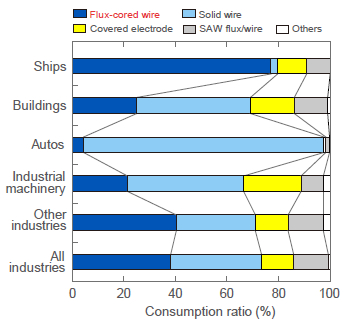
Figure 1: Relative consumption of welding consumables by industry in Japan in 2009.
As shown in Figure 1, in comparison with other industries in Japan, shipbuilding sees the highest relative consumption of f lux-cored w ires ( FCWs). This is because FCW offers higher deposition rates over other types of filler metals, thereby improving welding efficiency. FCW also offers high usability in all positions, which benefits ship hull fabrication as hulls consist of large components with flat, vertical, overhead, and curved welding lines. Because hull structures have many confined a reas t hat a re d ifficult t o a ccess, onesided welding by FCW is common.
Submerged arc welding (SAW) consumables are also used at a high ratio for one-sided welding of butt joint of large shell plates.
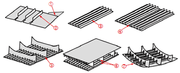
Figure 2: Typical assemblies and the major welding lines at
the sub-assembly and assembly stages.
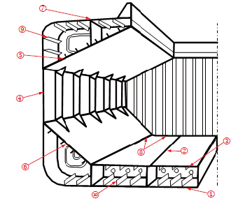
Figure 3: The typical cross sectional structure of a bulk carrier and the major welding lines at the erection stage.
Figure 2 and Table 1 show the typical welding assemblies and procedures for major welding joints at the sub-assembly and assembly stages. Figure 3 and Table 2 show the cross sectional structure of a bulk carrier and the typical welding procedures for major welding joints at the erection stage.
| Joint No. |
Assembly stage |
Component, Joint type |
Welding position |
Welding process |
FAMILIARC™ welding consumables | Remarks | |
|---|---|---|---|---|---|---|---|
| For D-grade steel | For E-grade steel | ||||||
| ① | Subassembly | Flat plate, Butt joint |
Flat | Doublesided SAW |
US-36/PF-H55E | Automatic | |
| ② | Stiffener, Fillet joint |
Horizontal | FCAW | ▪MX-200 ▪DW-200 |
▪MX-200E ▪DW-200 |
Portable welder | |
| ③ | Assembly | Longitudinal member, Fillet joint |
Horizontal | FCAW | ▪MX-200 ▪MX-200H ▪MX-200HS |
▪MX-200E ▪MX-200H ▪MX-200HS |
Line welder |
| ④ | Panel plate, Butt joint |
Flat | One-sided SAW |
US-36/PF-I55E/PF-I50R | FCB™ process | ||
| US-36/PH-I55E/RF-1 | RF™ process | ||||||
| ⑤ | Slot/transverse member, Fillet joint |
Horizontal, Vertical |
FCAW | DW-100V | DW-55E | Robotic | |
| ⑥ | Double bottom inside, Fillet joint |
Horizontal, Vertical |
FCAW | DW-100 | DW-55E | Semi-automatic | |
| ⑦ | Curved plate, Butt joint |
Flat | One-sided SAW |
US-36/PF-I52E/FA-B1 | FAB™ process | ||
| One-sided FCAW |
DW-100/FB-B3 | DW-55E/FB-B3 | Semi-automatic | ||||
| Joint No. |
Block name, Type of joint | Welding position |
Welding process |
FAMILIARC™ welding consumables | Remarks | |
|---|---|---|---|---|---|---|
| For D-grade steel | For E-grade steel | |||||
| ① | Bottom shell, Butt joint | Flat | One-sided FCAW | DW-100/FB-B3T | DW-55E/FB-B3T | Semi-automatic |
| ② | Tank top, Butt joint (longitudinal) |
Flat | One-sided SAW | US-36/PF-I52E/RR-2/FA-B1 | FAB™ process | |
| One-sided GMAW | MG-50D/FB-B3 | Automatic GMAW | ||||
| ③ | Tank top, Butt joint (transverse) |
Flat | One-sided FCAW + SAW |
DW-100/FB-B3 + US-36/PF-H55E |
DW-55E/FB-B3 + US-36/PF-H55E |
Semi-automatic + SAW |
| ④ | Side shell, Butt joint | Vertical | EGW | HS-42G or DW-S43G/KL-4 | Automatic | |
| FCAW | DW-100V | ― | Semi-automatic | |||
| ⑤ | Top side tank’s bottom plate, Butt joint |
Flat | One-sided FCAW | DW-100/FB-B3 | DW-55E/FB-B3 | Semi-automatic |
| ⑥ | Bilge hopper, Butt joint |
Horizontal, Vertical |
One-sided FCAW | DW-100/FB-B3 DW-100V/FB-B3 |
DW-55E/FB-B3 | Semi-automatic |
| ⑦ | Upper deck, utt joint (transverse) |
Flat | One-sided FCAW + SAW |
DW-100/FB-B3 + US-36/PF-H55E |
DW-55E/FB-B3 + US-36/PF-H55E |
Automatic FCAW + SAW |
| ⑧ | Tank top, Fillet joint | Horizontal | FCAW | MX-200 | MX-200E | Portable welder |
| ⑨ | Longitudinal member, Butt joint |
Flat | One-sided FCAW | DW-100/FB-B3 | DW-55E/FB-B3 | Semi-automatic |
| ⑩ | Vertical | One-sided FCAW | DW-100/FB-B3 | DW-55E/FB-B3 | Semi-automatic | |
State-of-the-art welding processes and consumables
TRIFARC™ Process
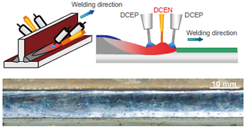
Figure 4: Schematic TRIFARC™ process and typical fillet weld bead appearance (Welding wire: FAMILIARC™ MX-200HS; 1.6 mmØ; Filler wire: FAMILIARC™ MG-1HS; 1.2 mmØ; Plate thickness: 12 mm; Welding speed: 2.0 m/min; Shop primer thickness: 30 μm).
The TRIFARC™ process is an advanced three-electrode fillet welding process that was developed to respond to customer needs for higher speeds as well as higher resistance to porosity in fillet welding. As shown in Figure 4, the TRIFARC™ process uses three electrodes, wherein the middle one carries DCEN current while the others carry DCEP. The middle electrode generates no arc but a specific magnetic field whose direction is opposite to those of the other two electrodes. The inverse magnetic fields can reduce the arc interference between the right and left electrodes, thereby allowing the two electrodes to carry higher welding currents and offer higher deposition rates. The magnetic effect of the central electrode can also stabilize both the d roplet t ransfer of the other t wo electrodes and the molten pool. This mechanism consistently enables welding speeds of up to 2 m/min. and excellent porosity resistance.
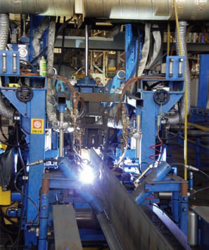
Figure 5: TRIFARC™ process in operation at
Sumitomo Heavy Industries Marine & Engineering
Co., Ltd., Japan.
The TRIFARC™ process uses a dedicated FCW, FAMILIARC™ MX-200HS, which offers higher deposition rates at the same welding current as compared with traditional FCWs. A new welding procedure that combines this advanced process and consumable results in welding speeds that are 1.2-1.5 times higher than conventional fillet welding procedures, and repair welding is unlikely due to excellent porosity resistance. This outstanding fillet welding procedure was first put into practice by a leading shipbuilder in May 2008 (Figure 5, above), and, since t hen, h as b een e xpanding i nto o ther s hipyards while gaining a high reputation.
Tandem-Electrode SEGARC™ Process
With the size of container ships getting ever larger, thicker steel plates are required for the hull components where high stresses concentrate: a maximum thickness of 80 mm for sheer strakes and hatch-combing side plates. For welding thicker steel joints at higher welding speeds with larger deposition rates, the tandem-electrode SEGARC™ process has been developed. This is a two-wire electrogas arc welding (EGW) process, which was developed from the single-electrode SEGARC™ process that has long been used in vertical upward welding in hulls due to its high efficiency and consistent weld joint properties.
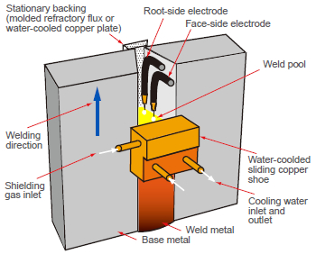
Figure 6: Schematic of the tandem-electrode SEGARC™ process with the root-side FCW and the face-side FCW.
As shown in Figure 6, the tandem-electrode SEGARC™ process uses two dedicated FCWs: FAMILIARC™ DW-S50GTF for the face side of the joint and FAMILIARC™ DW-S50GTR for the root side.
With this welding procedure, the weld metal possesses sufficient tensile strength equivalent to or higher than that of the base metal and offers consistent notch toughness and fracture toughness at high heat input. Figure 7 shows the cross sectional macrostructures of the weld joints. Table 3 shows the mechanical test results of the weld metals.
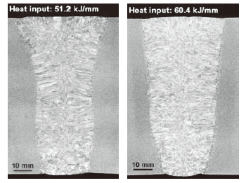
Figure 7: Cross sectional macrostructures of EGW welds
made with FAMILIARC™ DW-S50GTF + FAMILIARC™
DW-S50GTR (Plate thickness: 80 mm).
| Gap (mm) |
Heat input (kJ/mm) |
0.2% OS (MPa) |
TS (MPa) |
El (%) |
IV *2 (J at −20°C) |
|---|---|---|---|---|---|
| 8 | 51.2 | 503 | 644 | 24 | 123 (135, 115, 119) |
| 10 | 60.4 | 474 | 622 | 24 | 107 (86, 108, 127) |
| *1: Plate thickness is 80 mm and V-groove angle is 20 degrees. *2: Test specimens were removed from the weld metal center. |
|||||
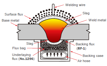
Figure 8: Diagram of the RF™ one-sided SAW process.
RF™ Process
The RF™ process is a highly efficient one-sided SAW process used for tapered joints, in particular those combining thicker and thinner steel plates. As the use of tapered joints increases to meet the CSR rules, the RF™ one-sided SAW process, one of Kobe Steel’s “Only- One”― unique and highly reputed ― technologies stands out. A diagram of the RF™ process is shown in Figure 8.
Figure 9 shows how to set up the welding joint and the cross sectional macrostructure of the weld joint. In Figure 10 (above) the entire set-up of the process equipment is displayed. As shown in Figure 8, the RF™ process uses a flexible flux backing that can maintain tight contact with the reverse surface of a weld joint even with a tapered transition. In addition to tapered joints, this process excels in welding thinner plates that are apt to be distorted by excessive heat.
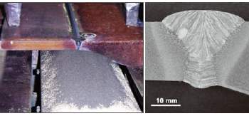
Figure 9: How to set up a tapered joint on the backing flux in
the RF™ process (left). The cross sectional macrostructure
of the weld joint (right) produced under the following
conditions:
▪ Plate thickness combination: 20 and 50 mm
▪ Welding process: RF™ one-sided SAW with 3 wires
▪ Welding wire: FAMILIARC™ US-36 (4.8 and 6.4 mmØ)
▪ Welding flux: FAMILIARC™ PF-I55E
▪ Backing flux: FAMILIARC™ RF-1
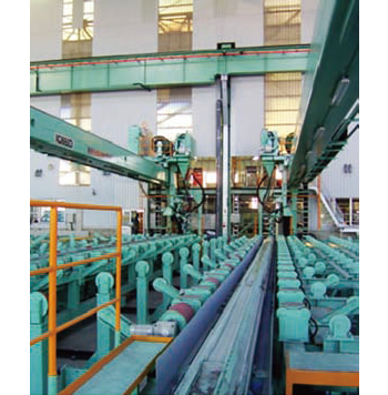
Figure 10: RF™ process setup for onesided submerged arc welding of a steel plate joint with a tapered transition.
YP460-Class Filler Metals
| Trade designation (Wire dia.) |
DW-460L (1.2 mmØ) |
DW-S460LG (1.6 mmØ) |
|
|---|---|---|---|
| Steel grade (Thickness) |
EH47 (60 mm) *2 | EH47 (60 mm) | |
| Groove preparation | 40°V, Gap: 6 mm | 20°V, Gap: 10 mm | |
| Welding process | FCAW (CO2) | EGW (CO2) | |
| Welding position | Flat | Vertical | Vertical |
| Heat input (kJ/mm) | 2-3 | 2-3 | 39.2 |
| 0.2% OS (MPa) | 573 | 630 | 501 |
| TS (MPa) | 630 | 681 | 648 |
| El (%) | 23 | 20 | 21 |
| IV (J) at −20°C *3 | 136 | 119 | 121 |
| *1: Test specimens were removed from the weld metal center. *2: Preheat and interpass temperature: 100-120°C. *3: The average value of three individual values. |
|||
In order to produce high-strength hull components while r educing h ull w eight, t hinner s teel p lates a re required. Instead of conventional YP390 class steels, YP460 class steels (with a minimum yield strength of 460 MPa) are now being used for this purpose. The YP460-class filler metals, TRUSTARC™ DW-460L (for semi-automatic FCAW) and TRUSTARC™ DW-S460LG (for the SEGARC™ process) meet the needs for welding components made of these steels.
Table 4 shows t he t ypical mechanical properties of DW-460L and DW-S460LG. DW-S460LG provides sufficient strength as compared with the base metal and offers excellent notch toughness and fracture toughness even at high heat input. Both FCWs feature welder-friendly usability, which makes them easy to work with.
Products
- Main Products
- Welding Consumables
- Arc welding robots
- Industries - Recommended Materials
- Welding Handbook Quick View
- Product Quick View & Highlights
- For HEAT-RESISTANT STEEL
- For STAINLESS STEEL
- For LOW-TEMPERATURE STEEL
- Product Highlight
- Catalog
- Technical Highlights
- Certification
- SDS ※English Only
- ARCMAN
- Welding Robot
- Software


