

- Home >
- Products >
- Technical Highlight >
- Vol.15: Supply and demand for LNG and implications for 7% Ni TMCP steel and welding consumables >
Technical Highlight Vol.15
Supply and demand for LNG and implications for 7% Ni TMCP steel and welding consumables

1. Preface
![Worldwide trends in LNG exports [1] Note: MTPA: Million tons per annum](../../images/education-center/technical_hightlight/vol15_fig01.png)
Figure 1: Worldwide trends in LNG exports [1]
Note: MTPA: Million tons per annum
Three and a half years after describing Kobelco’s welding consumables for liquefied natural gas (LNG) storage tanks made of 9% Ni steel in the Kobelco Welding Today, Vol.14, No.2, (KWT14-2) (2011) issue, the global market for LNG has changed significantly.
Not only has the supply and demand situation changed, but so have the properties of the steel used for storage tanks. 7% Ni Thermo Mechanical Control Process (TMCP) steel has successfully been introduced in Japan in order to reduce the Ni content, which is expensive and susceptible to fluctuations in the market. The specification of 7% Ni TMCP steel is already covered by Japanese Industrial Standard (JIS) regulations as well as non-Japanese specifications such as ASTM.
This article briefly introduces the welding consumables that are suitable for 7% Ni TMCP steels and provides some up-to-date technical data.
2. Recent LNG supply and demand
![Figure 2: Worldwide LNG exports in 2013 [2]](../../images/education-center/technical_hightlight/vol15_fig02.png)
Figure 2: Worldwide LNG exports in 2013 [2]
Figure 1 shows that LNG exports increased sharply in 2010. Total worldwide LNG exports in 2013 reached 237 million tons per annum (MTPA) as shown in Figure 2, reflecting an increase in global demand, mainly in Asia and particularly in China.
The export of LNG from floating storage units (FSUs) (Figure 1) is also a recent supply trend. In most cases, FSUs or floating storage and gasification units (FSRUs) are converted out of LNG ships, which reduces both cost and time associated with construction and, therefore, keeps up with the current supply and demand of LNG.
Situation in Asia
![Figure 3: Worldwide gas-liquefaction capacity [3]](../../images/education-center/technical_hightlight/vol15_fig03.png)
Figure 3: Worldwide gas-liquefaction capacity [3]
Due to the large increase in natural gas consumption, 7% Ni Thermo Mechanical Control Process (TMCP) has also increased and is expected to grow, particularly in Asia and the Pacific as shown in Figure 3.
Accordingly, the need for LNG storage yards and transportation systems such as LNG carriers (oceangoing and domestic) will increase.
Figure 4 shows China’s primary energy consumption plan, based on the twelfth five year plan (2011-2015). China’s LNG imports are forecast to increase 50% each year, from 14.7 million tons in 2012 to a maximum 100 million tons per year. Naturally, a large number of LNG terminals and LNG carriers (for oceangoing and domestic use) will be required in due course.
![Figure 4: Forecast of primary energy consumption in China [4] Note: *1: Million tons of oil equivalent.](../../images/education-center/technical_hightlight/vol15_fig04.png)
Figure 4: Forecast of primary energy consumption in China [4]
Note: *1: Million tons of oil equivalent.
LNG tanks are classified roughly into three types: Membrane, Moss and IMO (International Maritime Organization)-type A, B or C tanks. While membrane and Moss tanks are applied on oceangoing LNG carriers, the third type is for the smaller-sized, domestic carriers, as shown in Table 1. Figure 5 shows a typical domestic LNG carrier and Figure 6, some IMO–type C tanks.
| Type of LNG tank | |
|---|---|
| Oceangoing LNG carrier | Membrane and Moss |
| Domestic LNG carrier | IMO ‒ type A, B, C |
Figure 7 shows a newly-developed tri-lobe tank, which will be equipped on a liquefied ethylene gas (LEG) ship for the transport of LEG in the near future.
![Figure 5: Typical domestic LNG carrier [6]](../../images/education-center/technical_hightlight/vol15_fig05.jpg)
Figure 5: Typical domestic LNG carrier [6]
![Figure 7: Tri-lobe tank [6]](../../images/education-center/technical_hightlight/vol15_fig07.jpg)
Figure 7: Tri-lobe tank [6]
![Figure 6: IMO-type C tanks [6]](../../images/education-center/technical_hightlight/vol15_fig06.jpg)
Figure 6: IMO-type C tanks [6]
Development and specifications of 7% Ni TMCP steel
For safe operations under cryogenic conditions, LNG storage tanks are generally made of 9% Ni steel plates. Recently, however, 7% Ni TMCP steel plate has been developed, which reduces the content of expensive Ni by nearly 20%.
7% Ni TMCP steel was standardized as SL7N590 in JIS G3127, "Nickel steel plates for pressure vessels for low temperature services," in March 2013, when application of this product began in Japan. Around the same time in the USA, ASTM standardized 7% Ni TMCP steel as Gr. G Class 9 and Class 10 in A841, "Standard Specification for Steel Plates for Pressure Vessels, Produced by Thermo-Mechanical Control Process (TMCP)."
The JIS and ASTM specifications of 7% Ni TMCP and 9% Ni steels are shown in Table 2 for reference.
| Specification | ASTM | JIS G 3127 | |||
|---|---|---|---|---|---|
| A553 Type I | A841 Grade G | SL9N 590 | SL7N 590 | ||
| Cl.9 | Cl.10 | ||||
| Plate thickness (mm) | 50 max. | 50 max. | 100 max. | 50 max. | |
| Process | QT | TMCP | QT | TMCP | |
| C (%) | 0.13 max. | 0.13 max. | 0.12 max. | ||
| Si (%) | 0.15-0.40 | 0.04-0.15 | 0.30 max. | ||
| Mn (%)/td> | 0.90 max. | 0.60-1.20 | 0.90 max. | 1.20 max. | |
| P (%) | 0.035 max. | 0.015 max. | 0.015 max. | ||
| S (%) | 0.035 max. | 0.015 max. | 0.015 max. | ||
| Ni (%) | 8.50-9.50 | 6.00-7.50 | 8.50-9.50 | 6.00-7.50 | |
| 0.2%PS (MPa) | 585 min. | 585 min. | 620 min. | 590 min. | |
| TS (MPa) | 690-825 | 690-825 | 750-885 | 690-830 | |
| El (%); Thick(mm) | 20 min. | 20 min. | 21 min. (t ≤ 16) 25 min. (t > 16) |
||
| IV (J) at -196°C | 34 min. | 34 min. | 41 min. | ||
| LE*1 (mm) at -196°C | 0.38 min. | 0.38 min. (t ≤ 32) 0.48 min. (t=50)*2 |
- | - | |
| Note: *1: LE: Lateral Expansion *2: LE value between the plate thickness 32 and 50 shall be determined by linear interpolation. |
|||||
Results of tests comparing 9% Ni and 7% Ni TMCP steels are described below.
4-1. Basic features of 7% Ni TMCP steel
| Steel | 7% Ni TMCP | 9% Ni |
|---|---|---|
| Microstucture | 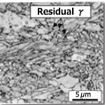 |
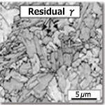 |
| Residual γ (%) | 8.5 | 3.2 |
In order to maintain the same high toughness as 9% Ni steel, TMCP technology allows for much residual austenite (γ) to be distributed in the base structure of 7% Ni TMCP steel.
As seen in Figure 8, the lath structure is refined in 7% Ni TMCP steel, resulting in the increase of residual γ.
4-2. Basic performance evaluation
Tests were carried out on several properties related to the basic performance of 7% Ni TMCP steel, as shown in Table 3. The test results shown in Tables 4 and 5 prove that 7% Ni TMCP steel performs as well as 9% Ni steel.
| Basic | Resistance to brittle fracture | |
|---|---|---|
| Plate | ・Tensile test | ・CTOD test |
| ・CTOD test | ・Duplex ESSO test | |
| Welded joint | ・Tensile test | ・CTOD test |
| ・CTOD test | ・Cross weld notched wide plate test |
| Steel | Thickness (mm) | 0.2%PS (MPa) | TS (MPa) | EL (%) |
|---|---|---|---|---|
| 7% Ni TMCP | 40 | 655 | 738 | 31 |
| 9% Ni | 36 | 726 | 743 | 23 |
| SL7N590 | 590 min. | 690-830 | 21 min. | |
| Note: Position: 1/4 t Direction: Parallel to rolling direction |
||||
| Steel | Thickness (mm) | IV (J)at -196°C | BA(%) at -196°C | |
|---|---|---|---|---|
| 7% Ni TMCP | 40 | Avg 256 | 0 | |
| 9% Ni | 36 | Avg 243 | 0 | |
| SL7N590 | 41 min. | - | ||
| Note: BA: Brittle fracture appearance value Position:1/4 t Direction: Parallel to rolling direction |
||||
4-3. Brittle fracture resistance
7% Ni TMCP and 9% Ni steels were compared for brittle fracture resistance, as shown in Table 3.
Resistance to brittle crack initiation and cracking were evaluated by CTOD test and a Duplex ESSO test, respectively. For reference, a schematic drawing of the Duplex ESSO test is shown in Figure 9. The results of both the CTOD and Duplex ESSO tests show basic equivalence between 7% Ni TMCP and 9% Ni steels as shown in Tables 6 and 7, respectively.
| Excellent property | Poor property |
|---|---|
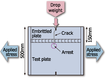 |
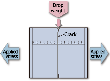 |
| Steel | Thickness (mm) | Critical CTOD value (mm) at -165°C | ||
|---|---|---|---|---|
| 7% Ni TMCP | 40 | 1.18; 1.05; 1.18 | ||
| 9% Ni | 36 | 0.65; 0.70; 0.68 | ||
| SL7N590 | 41 min. | - | ||
| Note: Direction: Parallel to rolling direction | ||||
| Steel | Thickness (mm) | Temperature (°C) | Applied stress (MPa) | Judgment |
|---|---|---|---|---|
| 7% Ni TMCP | 40 | -196 | 392 | No-Go |
| 9% Ni Steel | 36 | -196 | 392 | No-Go |
4-4. Properties of butt joint welding with 7% Ni TMCP steel
Double V butt joint welding was performed on 7% Ni TMCP steel plate using PREMIARC™ NI-C70S, 4 mm dia. covered electrodes in the vertical upward position (3G). The welding conditions are shown in Table 8.
| Direction of welding | Welding process | Product name | Φ mm | Welding position | Heat input (kJ/mm) |
|---|---|---|---|---|---|
| Transverse to rolling direction | SMAW | NI-C70S | 4.0 | 3G uphill | 4.4 max. |
Figure 10 shows the schematic cross-sectional weld metal and location of notch toughness test specimens.
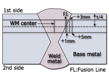
Figure 10: Schematic location of test specimens
The notch toughness test results are shown in Figure 11. All values fulfill the requirement of SL7N590 (34J min. and 41J average at -196°C).
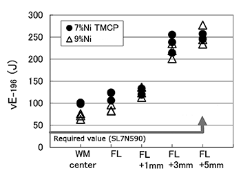
Figure 11: Results of notch toughness tests
4-4-2 Brittle fracture resistance
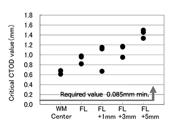
Figure 12: Results of CTOD tests
Resistance to brittle fracture was tested by CTOD, and all values were found to exceed the requirements of a 140,000m³ LNG tank (0.085 mm min. at -196°C) as shown in Figure 12.
Welding consumables for 7% Ni TMCP steel
All welding consumables recommended by Kobe Steel for 9% Ni steels are also suitable for welding 7% Ni TMCP steels without exception. Typical welding consumables recommended for 7% Ni TMCP steels are listed in Table 9.
5-1. PREMIARC™ DW-N709SP
The AWS specification (A5.34) of ENiMo13-T, under which PREMIARC™ DW-N709SP is included, has formally been issued. It is now classified as ENiMo13T1-4/0-1 as shown in Table 9. Recent test results of welding by DW-N709SP and of comparing the efficiency of DW-N709SP with that of a covered electrode are described below.
| FCAW | SMAW | GTAW | SAW | |
|---|---|---|---|---|
| Product name | DW-N709SP | NI-C705 | TG-S709S | PF-N4 (flux) / US-709S (wire) |
| Features | ・Hastelloy type ・Ar-CO2 gas for all position welding and CO2 gas, for 1G, 1F and 2F welding |
Inconel type | ・Hastelloy type ・Suitable for automatic-TIG welding |
・Hastelloy type ・Suitable for 2G position welding |
| Polarity | DCEP | AC | DCEN | DCEP |
| Ni (%) | 62.5 | 63.4 | 70.4 | 64.0 |
| Cr (%) | 6.5 | 16.6 | 2.0 | 1.7 |
| Mo (%) | 17.6 | 5.3 | 19.0 | 17.2 |
| W (%) | 2.4 | 0.7 | 3.0 | 2.7 |
| Nb+Ta (%) | - | 1.1 | - | - |
| Fe (%) | 7.9 | 9.9 | 5.5 | 14.9 |
| 0.2%PS (MPa) | 447 | 430 | 460 | 410 |
| Ts (MPa) | 723 | 705 | 730 | 680 |
| El (%) | 51 | 41 | 47 | 43 |
| IV(J) at -196°C | 89 | 62 | 160 | 70 |
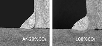
Figure 13: Comparison of horizontal fillet welding by shielding gas
As seen in Figure 13, Ar-CO2 shielding gas does not provide sufficient penetration at the corner in horizontal fillet position (2F) welding. When full penetration is required, 100%CO2 shielding gas is recommended.
5-2. Butt joint welding on 10 mm thick plate
| Product name | DW-N709SP | ||
|---|---|---|---|
| Shielding gas & flow rate | 80%Ar-20%CO2 & 25l/min | ||
| Welding position | 3G uphill | ||
| Interpass temperature | 150°C max. | ||
| Polarity | DCEP | ||
| Welding parameters | Face side | 1st layer | 140A-24V-17 cm/min |
| 2nd layer | 160A-26V-16 cm/min | ||
| Back side | Final layer | 160A-26V-15 cm/min | |
Butt joint welding in the 3G position was conducted on a 10mm thick plate. The welding conditions are shown in Table 10, the groove shape and macro structure, in Figure 14 and the welded joint properties, in Table 11, respectively.
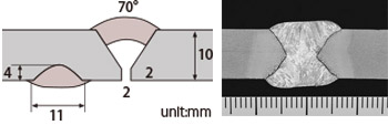
Figure 14: Groove configuration and macro structure
| Properties | Measurements |
|---|---|
| TS (MPa) | 759; 764 (Fractured at base metal) *1 |
| Notch toughness (J) at -196°C | 62, 65, 60 (Avg. 62) *2 |
| Longitudinal bending, 180° | No defect |
| Note: *1: Due to plastic constraint, the weld metal strength is increased. *2: Specimen size is 7.5mm x 10mm |
|
5-3. Welding efficiency comparison of SMAW and FCAW (DW-N709SP)
| DW-N709SP (1.2mmΦ) | SMAW (4mmΦ) | |
|---|---|---|
| Product quantity (kgs) | 125 | 200 |
| Arc time (hour) | 29.4 | 71.4 |
| Deposition rate (g/min) | 75 (at 200 A) | 34 (at 150 A) |
| Deposition efficiency (%) | 85 | 50 |
SMAW and DW-N709SP were compared in terms of the product quantity and arc time needed to obtain 100 kgs of weld metal. Table 12 shows the results. DW-N709SP was found to be excellent in deposition rate, arc time as well as deposition efficiency.
Notes on usage
When using 7% Ni TMCP steels, users must take the same precautions they would for 9% Ni steels, which were described in KWT14-2.
(1) Easy magnetization
Residual magnetism in 7% Ni TMCP steel will cause magnetic arc blow. For welding, it is advisable to use AC polarity as much as possible for SMAW and SAW.
(2) Crater crack
It is strongly recommended that users grind the crater down each time the arc stops, in order to avoid crater cracks.
(3) Dilution
Dilution of the base metal into the weld metal by the arc causes changes in the weld metal chemistry, resulting in the decrease of weld metal tensile strength. Users must ensure that the tensile strength and 0.2% proof strength fulfill the requirements in the procedure test in advance.
Postscript
This article discussed the recent global supply and demand of LNG as well as the application of 7% Ni TMCP steel for cryogenic uses. As a clean source of energy, the natural gas demand is expected to increase further, requiring the development of many new technologies. Kobe Steel will continue cultivating new welding technologies, in accordance with the needs of our users.
References
[1]-[4] JOGMEC (Japan Oil, Gas and Metals National Corporation), Trend of LNG, 2014
[5] Kobe Steel engineering reports, Vol. 64, No. 1 (2014)
[6] Sinopacific Offshore & Engineering Co., Ltd.
Products
- Main Products
- Welding Consumables
- Arc welding robots
- Industries - Recommended Materials
- Welding Handbook Quick View
- Product Quick View & Highlights
- For HEAT-RESISTANT STEEL
- For STAINLESS STEEL
- For LOW-TEMPERATURE STEEL
- Product Highlight
- Catalog
- Technical Highlights
- Certification
- SDS ※English Only
- ARCMAN
- Welding Robot
- Software


