

- Home >
- Products >
- Technical Highlight >
- Vol.22: ARCMAN™ Robotic Welding System for Hull Assembly in Shipbuilding
Technical Highlight Vol.22
Vol.22: ARCMAN™ Robotic Welding System for Hull Assembly in Shipbuilding

1.Preface
Kobe Steel’s Welding Business provides customers with excellent products and services that support their Monodzukuri (production system innovation) capabilities, while aiming to remain the most reliable enterprise for total welding solutions in the world. I n accordance with our latest 2016-2020 mid-term management plan, welding automation for the shipbuildi ng industry has been making progress as one of the solution businesses.
In many industries, including shipbuilding, a lack of skilled welders has been of increasing concern as the field sees older welders retire without attracting enough younger ones; accordingly, the need for multi-skilled workers and/or labor-saving systems is urgent in order to increase production efficiency.
This article will discuss a newly-developed robotic welding system for hull assembly in shipbuilding that raises productivity.
2.Features of a robotic welding system for hull assembly
2.1 ARCMAN™ robotic welding system
Almost all large steel ships have been built by the block construction method in recent years.
Block construction involves dividing a planned ship into several blocks, prefabricating the blocks at a shipyard assembly plant (Figure 1) before affixing them on a dock or a slipway. The prefabrication of each block – or section of a ship – includes steel cutting, processing and finishing the sub-assembly on an assembly line before the block is moved to a dock or a slipway for block-to-block joining.
Figure 2 shows a perspective view of joined blocks and the welding lines inside blocks (circled area), which are located in the parallel portions (excluding curved portions) of a ship.
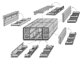
Figure 1: Schematic outline of sub-assembly and assembly in the prefabrication of a block for hulls
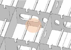
Figure 2: Perspective view of joined blocks and welding lines inside blocks
The ARCMAN™ robotic welding system is designed to be applied in enclosed spaces inside the blocks of a ship’s parallel-portion. An arrangement of ARCMAN™ robots is shown in Figure 3.
One important design factor is that a robot should fit in the narrow space inside a block. Therefore, the new robot is small enough to be set and able to weld in a space as narrow as that shown in Figure 4.
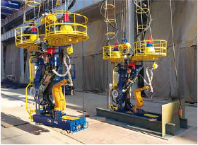
Figure 3: Arrangement of ARCMAN™ robots
Figure 4: Extremely small-sized ARCMAN™ robot and robot-carry (the ARCMAN™ set) for narrow spaces
The small-sized ARCMAN™ robot is mounted on a robot-carry that is designed to be light in weight for easy transportation. The robot and robot-carry (hereinafter called the ARCMAN™ set) is hooked to a crane, and can be transported between blocks as shown in Figure 5. The ARCMAN™ set is lowered into a block until the robot-carry touches down upon the bottom plate. The robot-carry then sets its position with an automatic positioning device. Afterwards, the robot selects the target program and starts welding.
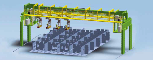
Figure 5: The ARCMAN™ robot and robot-carry (the ARCMAN™ set) arrangement for a block
Controlling the welding robot is the new “CB type” controller, which has more functions, is simpler to operate and performs better than conventional controllers. Some notable features include arc sensing technology that enables the tracing of distortion caused by welding heat(one of the ARCMAN™’s strongest advantages), vibration damping control technology, an abundance of pre-installed welding conditions, simpler operability and excellent responsiveness of the teaching pendant. Improved safety and maintenance features as well as extras like sliders and positioners that allow for integration with other systems add to the attractiveness of the ARCMAN™ system.
Figures 6 and 7 show the ARCMAN™ set, being transported to an actual application site, while hooked to a crane, and the one, setting its position with an automatic positioning device after lowered on to a bottom plate, respectively.
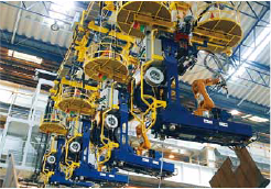
Figure 6: The ARCMAN™ set is transported to an actual application site, while it is hooked to a crane.
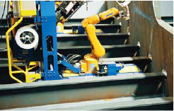
Figure 7: After lowered on to a bottom plate,the ARCMAN™ set fixes its position.
Figures 8 and 9 show the welding operation at an actual application site, respectively.
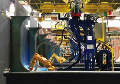
Figure 8: The ARCMAN™ set started welding.
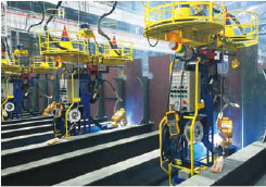
Figure 9: The ARCMAN™ set’s welding is in operation.
2.2 Application of the ARCMAN™ robotic welding system
The ARCMAN™ robotic welding system has been designed to be applied in a space enclosed by a longitudinal member and a transverse member as shown in Figure 10.
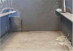
Figure 10: Enclosed space for ARCMAN™ robotic welding system application
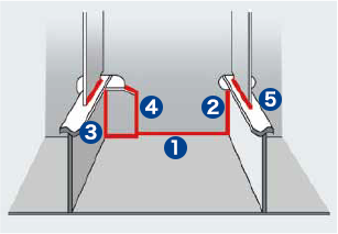
Figure 11: Illustration of the welding lines inside a space such as Figure 10
Figure 11 illustrates the confined space shown in Figure 6, with Nos. ❶ to ❺ representing the welding lines to be welded by the ARCMAN™ system.
❶ Horizontal fillet welding between a bottom plate and a transverse member, and between a bottom plate and a collar plate
❷ Vertical-upward fillet welding between the web of a T-type longitudinal member and a transverse member.
❸ Vertical-upward fillet welding between a collar plate and the web of a T-type longitudinal member.
❹ Vertical-upward fillet welding between a collar plate and a transverse member.
❺ Horizontal fillet welding between a stiffener and the face of a T-type longitudinal member.
The vertical upward fillet welding of the web of a longitudinal member ( ❷ and ❸ in Figure 11) and the horizontal fillet welding of a stiffener ( ❺ in Figure 11), can tolerate a gap of up to 5 mm. At all corners of the welding lines, boxing welding (see Figure 15) is programmed to be applied.
2.3 Teaching software: SMART TEACHING™
At the parallel-portion of a ship, many linear members are installed in parallel. However, though similar, their sizes are so different that the ARCMAN™ system cannot be programmed via typical robot teaching. On the other hand, by integrating data from 3D models, an effective teaching method has been developed.
Designing with 3D models is now common in many industries, including shipbuilding, where 3D design has been used to identify problematic structural members or to check whether one member interferes with other members or not.
The offline teaching software “SMART TEACHING™” developed for the ARCMAN™ set utilize 3D models of ship-blocks for robot teaching. The ARCMAN™ set can easily create a robot teaching program with 3D model data in three steps:
(1) Loading 3D model data
(2) Automatically selecting the welding line to be welded inside an enclosed space of a ship block
(3) Programming the robot teaching system
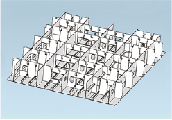
Figure 12: Typical 3D model
The 3D model data uses the versatile “Standard for the Exchange of Product” (STEP) format rather than CAD in order to maintain flexibility. Figure 12 shows a typical 3D model.
To extract a particular welding line out of multiple lines,the program analyzes and applies the information of a certain shape of a space in the 3D model data, utilizing the versatile STEP format mentioned above. The program studies the shapes in each enclosed space, and recognizes the intersections made by the longitudinal and transverse members as fillet welding joints to be welded.
The coordinate data in relation to the joint as well as the shape of the enclosed space are accumulated as the welding information data of the particular welding line. Figure 13 shows how the software displays the data of a selected welding line and the shape of an enclosed space.
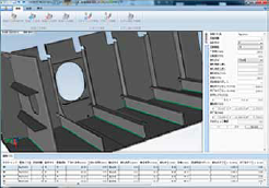
Figure 13: The software interface showing a selected welding line and the shape of an enclosed space
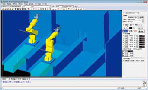
Figure 14: Welding simulation of the robot teaching program
The robot teaching program is prepared as follows:
(1) The welding start and finish points are established, based on the welding information data.
(2) The robot’s movements for conducting welding are prepared.
(3) Additional movements, such as touch sensing corresponding to the shape of the enclosed space, are entered.
(4) The welding parameters corresponding to the shape of the enclosed space and the welding position are selected.
After the robot teaching program is prepared, the software can display a simulation of the program (see Figure 14).
Because it is difficult to use software to calibrate position errors between positions designated by the teaching program and real work-piece positions, a positioning device is installed in the robot-carry.
Once the teaching program has been entered in each robot, welding can be started at any time.
2.4 Welding
Of all stages in the shipbuilding process, assembly requires the most welding and accounts for over 50% of the total consumption of welding consumables. As for welding consumables, rutile type flux cored wires (FCWs) account for the highest amount of consumption.
Kobelco’s representative FCWs for shipbuilding are  DW-100 and DW-100V. Both are for all position welding though the latter is particularly excellent at gap resistance at vertical upward welding.
A number of tests comparing the performance of these two FCWs in robotic welding for a ship have found that DW-100 would be the better choice in horizontal-fillet and vertical-fillet welding as well as horizontal-boxing fillet welding.
In one set of tests, DW-100 performed better in relation to the arc tracing function, which is a fundamental property in robotic welding. The tests examined arc tracing with and without inclination; joint gap resistance, which is common at the hull assembly stage; and also tapered gap resistance in vertical position welding.
In other tests, use of DW-100 resulted in better bead appearance. This was true for the beads at the connection between vertical upward and horizontal fillet welding, as well as at the connection between horizontal fillet-boxing welding and horizontal fillet welding (see Figure 15).
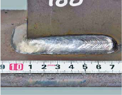
Figure 15: Weld connection between horizontal fillet-boxing welding and horizontal fillet welding
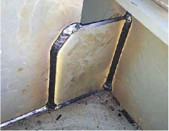
Figure 16: Bead appearance by robotic welding with DW-100
These tests have shown that DW-100 satisfies the demands of both horizontal-fillet and vertical-fillet welding as well as horizontal-boxing fillet welding. Figure 16 shows the bead appearance by robotic welding with DW-100.
In addition to improving the quality of welds produced in the vertical upward direction, increasing efficiency of vertical upward welding can improve block welding as a whole because it occupies a large amount of time in the block assembly stage.
Therefore, such efforts to improve productivity as by shortening the sensing time that corrects errors during work-piece assembly, increasing welding speeds, and improving gap treatment quality are a focus of ongoing development. For example, a new back-and-forth weaving function installed in the ARCMAN™ robot combined with the CB type controller enables the arc voltage to be set at both vertical and flat member sides independently. Welding procedure experiments such as these will further contribute to improve the quality of horizontal fillet welding.
* : FAMILIARC™, our Trade Designition
3.Future plan
In March 2014, the Industrial Internet Consortium (IIC) was established by five American companies - AT&T, Cisco Systems Inc., GE, Intel and IBM – in order to create standards related to Internet of Things (IoT). It has subsequently been joined by other enterprises and organizations in the USA, Germany and Japan.
These companies aim to promote automation and productivity through remote operation of machinery,while collecting operational data through sensors and networks. Other aims include raising operational efficiency and decreasing maintenance costs through data analysis. These technologies will be established as de facto standards, eventually helping to realize the platform in which the data of other companies’ machinery and devices is installed.
On October, 2016, the IoT Acceleration Consortium (ITAC) in Japan concluded memorandums of understanding for IoT cooperation with the Industrial Internet Consortium (IIC), the USA.
It is believed that Japan will accelerate its activities aimed at realizing the next industrial revolution by advancing these efforts in the field of IoT.
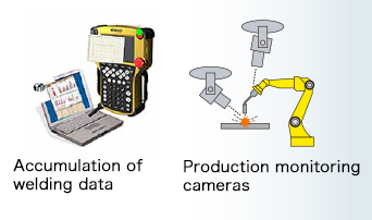
Figure 17: New programs in the CB type controller
Kobe Steel is also helping to promote the process of informatization. AP-SUPPORT™, software for production support, allows for the visualization of operational data, thereby, preventing errors such as moment stops and improving productivity.
New programs have been installed in the CB type controller that can reduce welding errors by accumulating operational data through arc monitoring and grasping situational details through the use of production monitoring cameras. Figure 17 shows examples of these new programs.
4.Postscript
This article discussed the ARCMAN™ robotic welding system for the hull assembly stage in shipbuilding. The ARCMAN™ set combines a welding robot and robot carry that enables welding in the confined and narrow space inside blocks with a robot teaching system that contains optimum welding parameters and robot movement information.
The ARCMAN™ system can raise the efficiency of operations hampered by limited workforces and improve productivity at various welding stages.
Aiming to remain as the premier welding solutions company, we will continue to develop not only our line-up of welding consumables but also panel line technology such as robotic welding systems for hull assembly and sub-assembly fabrication.
Products
- Main Products
- Welding Consumables
- Arc welding robots
- Industries - Recommended Materials
- Welding Handbook Quick View
- Product Quick View & Highlights
- For HEAT-RESISTANT STEEL
- For STAINLESS STEEL
- For LOW-TEMPERATURE STEEL
- Product Highlight
- Catalog
- Technical Highlights
- Certification
- SDS ※English Only
- ARCMAN
- Welding Robot
- Software


