

- Home >
- Products >
- Technical Highlight >
- Vol.24: Hybrid Tandem MAG Welding Process: An effective porosity-reduction method for welding primer-coated steel plates
Technical Highlight Vol.24
Vol.24: Hybrid Tandem MAG Welding Process: An effective porosity-reduction method for welding primer-coated steel plates

1.Preface
In shipyards and bridge construction, shop-primer is generally applied on a steel plate surface to temporarily prevent rust during block fabrication. However, when a primer-coated steel plate is welded, the primer often generates porosity (blow holes and pits) because the arc heat pyrolytically decomposes the primer film, which evaporates and generates gas that gets trapped in the weld metal in the process of solidification as shown in Figure 1.
a) Bead appearance
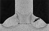
(b) Cross-sectional macrostructure
(c) Observation of fractured surface
Figure 1: Porosity defects caused by welding a primer-coated steel plate
In order to improve porosity resistance in welding of primer-coated steel plates, research has investigated adjusting the composition of primers used on steel points1), adjusting the slag formers in welding consumables2-4), and even developing an efficient tandem welding process in which the same flux cored wires (FCWs) with suitable chemical compositions5) are applied for both electrodes. However, despite investigating steels, welding consumables and welding processes, the research has yet to find a fully satisfactory solution to the problems described above.
On the other hand, new research studies have allowed the author*1 to better understand the mechanism of porosity generation by direct observation of porosity with X-rays and by experiments seeking to correlate the relationship between porosity and penetration depth. As a result, a new method that emits generated gas out of the weld metal at an early stage has been developed. Called the new Hybrid Tandem MAG welding process, it combines the usage of a solid wire as the leading electrode (LE) to get deeper penetration and an FCW as the trailing electrode (TE) to achieve a smooth bead surface.
2.Effects of welding primer-coated steel plates by a conventional welding process
Tests of horizontal fillet welding utilized frequently in shipyards and bridge construction were performed that obtained 7 mm leg length with FCWs and 100% CO2 shielding gas in both conventional single-electrode and tandem-electrodes processes. The welding conditions are shown in Table 1.
| Type of coating & film thickness | Non-organic zinc primer; 30μm | ||
|---|---|---|---|
| Shielding gas | 100%CO2 | ||
| Welding process | Single | Tandem | |
| Electrode | - | Leading (L) | Trailing (T) |
| Welding wire/Dia (mm) | FCW/1.4 | FCW/1.6 | FCW/1.6 |
| Distance between contact tip end and base metal (mm) | 25 | 25 | 25 |
| Torch angle θ1 (°) | 45 | 45 | 45 |
| Torch angle θ2 (°) | 0 | 7 (declined backward) |
7 (declined forward) |
| Welding current (A)/ arc voltage (V) |
330/34 | 430/32 | 320/30 |
| Welding speed (mm/min) | 400 | 1000 | |
| Distance between electrodes (mm) |
- | 25 | |
After welding, radiographic testing (RT) was conducted on the test specimens as shown in Figure 2. The observation results of both single- and tandem-electrode welding processes are shown in Figure 3.
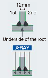
Figure 2: RT method
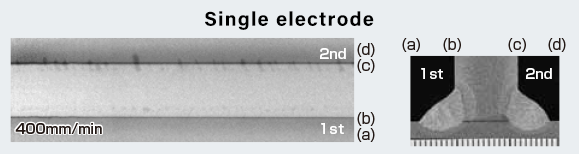
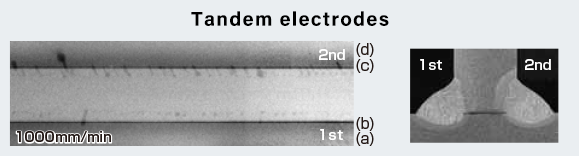
Figure 3: RT result in single- and tandem-electrodes welding processes
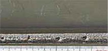
When an X-ray is irradiated at the top of a test specimen,as shown in Figure 2, blow holes appear darker than the surrounding weld in the X-ray film. In Figure 3, a number of blow holes can be observed in the fillet welds obtained from both welding processes; tellingly, the blow holes are initiated at the underside of the vertical member that touches the surface of the horizontal member (hereinafter called the underside of the root) and appear in a line along the underside of the root. Also, more porosity appears at the second side than that at the first side because the evaporated gas emits only from the second side during welding as the first side is closed by the weld.
3.Development of a porosity-reduction method
Research on welding Zn-coated thin steel sheets has shown that obtaining deep penetration right under the arc by adjusting shielding gas components, pulsed wave forms and/or welding wire chemical compositions can reduce porosity as most of the Zn gas is emitted directly under the arc6-8). The author has, therefore, developed a porosity-reduction method suitable for horizontal fillet welding by assuming that the mechanism for generating porosity in welding primer-coated steel plate must be the same as that for Zn-coated steel sheet.
It is believed that in the conventional process, vaporized primer enters the molten pool, causing porosity, starting at the root. The author therefore hypothesized that porosity will not be generated if the underside of the root is completely melted; in other words, if the unmelted part of the underside of the root is reduced to zero, 100% of primer shall be vaporized and emitted. Therefore, deep and stable penetration is essential in order to eliminate the entire unmelted part.
In the current research, several horizontal fillet welding methods that obtain deep and stable penetration were studied. By changing welding parameters, it was possible to look at how penetration depth and the amount of unmelted material influence the occurrence of blow holes. These mechanisms of porosity generation were verified by using an X-ray transmission type high speed video camera.
4.Factors influencing penetration depth
Because earlier research had shown that the LE electrode controls penetration depth in tandem welding9-10), it was decided to study the effect of such factors as the LE’s torch angle, welding current and arc voltage on penetration depth. The welding conditions are shown in Table 2; definitions for total penetration depth (LPene), the unmelted part of the underside of the root (LRoot) and leg length (LLeg) are shown in Figure 4.
| Steel plate & type of coating: film thickness | SM490A 12mm & Non-organic Zinc primer: 30μm | |
|---|---|---|
| Shielding gas | 100%CO2 | |
| Electrode | LE | TE |
| Welding wire (mm Dia) | Solid wire: 1.6 | FCW: 1.4 |
| Distance between contact tip end and base metal (mm) | 13 | 25 |
| Torch angle θ1 (°) | 5-45 | 45 |
| Torch angle θ2 (°) | 7 (declined backward) |
7 (declined forward) |
| Welding current (A) | 350-550 | 300-370 |
| Arc voltage (V) | 20-35 | 30-37 |
| Welding speed (mm/min) | 1000 | |
| Distance between electrodes (mm) | 30 | |
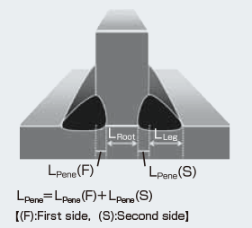
Figure 4: Definition of LPene, LRoot and LLeg
Figure 5 shows the relationship between the LE’s torch angles and LPene (F), the penetration depth at the first side.
It was found that as penetration direction gradually changes, the LPene (F) becomes larger, and was particularly optimal when θ1 is changed from 45° to 20°. After this finding, the LE torch angle θ1 was fixed to 20° to prevent the torch from interfering with the flat member. The relationship between the LE’s welding current and penetration depth is shown in Figure 6. It indicates that the higher the LE’s welding current is, the deeper the LPene is.
Figure 5: Relationship between the LE’s torch angles and LPene (F) penetration depth
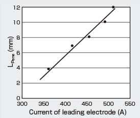
Figure 6: Relationship between the LE’s welding current and penetration depth
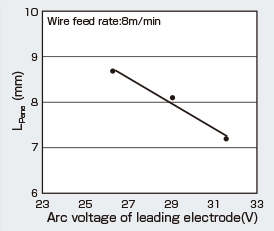
Figure 7: Relationship between LE’s arc voltage and LPene
Figure 7 shows the relationship between the LE’s arc voltage and penetration depth. With the LE’s wire feeding speed fixed at 8 m/min, the influence of the LE’s arc voltage on penetration depth was investigated by changing the arc voltage from buried arc (holding the arc length extremely short) to open arc (holding the arc length extremely long). As a result, it was found that the lower arc voltage was associated with a deeper buried arc and increased LPene.
5.Relationship between the occurrence of blow holes and penetration depth
5-1. Effect of LPene on the occurrence of blow holes
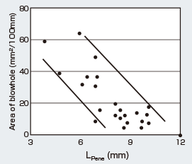
Figure 8: Relationship between LPene and the occurrence of blow holes
As shown in Figure 8, the number of blow holes decreases as LPene deepens, suggesting that deeper penetration is advantageous in reducing porosity. It is presumed that the primer-vaporized gas is more efficiently emitted right under the arc.
5-2. Influence of the unmelted underside of the root (LRoot) on the occurrence of blow holes
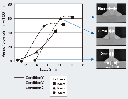
Figure 9: Relationship between LRoot and concentration of blow holes
In order to study the effect of LRoot on the occurrence of blow holes, horizontal fillet welding was performed in which welding parameters were kept constant while the plate thickness of vertical members was changed from 9mm to 12mm and 16mm. In order to maintain the same welding parameters, the LPene was held constant and only the LRoot was changed. After welding, the blow holes in the specimens were compared by using RT films. Figure 9 indicates that there is a tendency for blow holes to increase in number when the LRoot gets bigger. The result was obtained under all tested welding conditions. It is presumed that as LRoot becomes larger, the amount of gas remaining at the root part of both members increases, causing blow holes to occur.
5-3. Summary of influence of each factor
From the experiments carried out, two suggestions emerge in relation to reducing porosity:
As long as plate thickness is kept constant, the two points above mirror each other. However, as were shown in the preliminary tests, the measures to reduce porosity are to apply a) high welding current, b) low arc voltage and c) low torch angle (θ1) to the LE. By combining a) and b) one may apply a buried arc.
6.Observing the generation of porosity
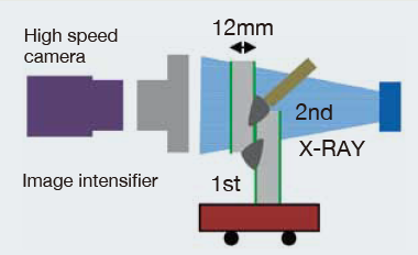
Figure 10: Observation method using X-ray transmission
In order to observe the formation of blow holes, their behavior inside a molten pool during welding was observed in the welding of a 12 mm-overlapped fillet weld joint by using an X-ray transmission type high speed video camera as shown in Figure 10.
6-1. Behavior of blow holes under an open-arc
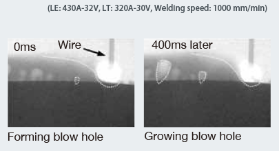
Figure 11: Formation of blow holes in a conventional welding process
When using a conventional welding process that applied long arc length at the LE, equivalent to an open-arc state, it was observed that porosity (blow holes and pits) began forming at the root part while evaporated primer gas at the unmelted part of the underside of the root intruded into the molten pool just behind the arc (see Figure 11). On the other hand, at the solidifying side (rear side) of the molten pool, the phenomenon of either gas emission or gas elimination was not observed.
6-2. Behavior of porosity under a buried arc
When the LE’s arc length was kept extremely short, as shown in Figure 12, it could be seen that the wire end was buried into the molten pool, causing the arc force to penetrate more deeply into the base metal. It appears that porosity will not occur inside the molten pool under such conditions. The reason is likely to be that as the molten pool right under the arc is pushed backward and reduced its thickness, the force suppressing the primer gas decreases against the pressure of the primer gas itself,
resulting in the primer gas being emitted from the molten pool. In other words, the route for emitting primer gas out from the molten pool is secured (Figure 13).
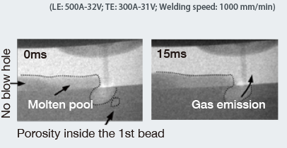
Figure 12: Observation of gas emission phenomenon by the newly developed process
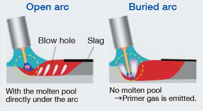
Figure 13: Mechanism of porosity reduction
Furthermore, when full penetration was achieved, even though a few blow holes remained at the bottom of the first-side weld, it was noticed that porosity-causing gas was emitted from the second-side molten pool.
7.Development of the hybrid tandem MAG welding process
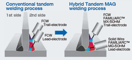
Figure 14: Structural comparison of conventional and new HTM welding processes
While these experiments have shown that a buried arc improves porosity resistance, a drawback to the buried arc is that it causes poor bead appearance. With these concerns in mind, the Hybrid Tandem MAG welding process (HTM process) has been developed in order to reduce porosity by using a buried arc while maintaining proper bead shape. The system’s structure is shown in Figure 14 11).
The process applies FAMILIARCTM MG-50HM (Solid wire 1.6 mm dia) to the LE for deep penetration and FAMILIARCTM MX-50HM (FCW 1.4 mm dia) to the TE for smooth bead appearance. Furthermore, the LE’s torch is declined 20° backward, for gaining the deepest penetration, and the TL’s torch, 45° forward for obtaining stable and excellent bead appearance. In addition, the LE utilizes a high ratio of welding current/arc voltage, to obtain a buried arc at the large welding current. Figure 15 shows the porosity resistance and shape of penetration, and Figure 16, the bead appearance by the HTM process. No porosity was generated at the first as well as second sides and excellent bead shape was also obtained.
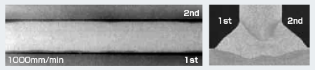
Figure 15: RT result (X-ray film) and shape of penetration by the HTM process
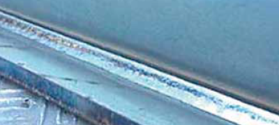
Figure 16: Bead appearance by the HTM process
8.Postscript
It was hypothesized that, for horizontal fillet welding on primer-coated steel plates, deep penetration as well as minimizing the unmelted underside of the root are important in order to reduce porosity generation. Experimental results were confirmed by direct observation inside molten pools with X-ray transmission type high speed video camera.
The new “Hybrid Tandem MAG welding process” achieves excellent porosity resistance by providing a mechanism for emitting vaporized gas. Dividing two respective functions into two electrodes, it equips the LE with a solid wire for deep penetration and the TE with a FCW for stable and excellent bead shape. The author wants to contribute to high quality and efficiency of welding in the fields of shipbuilding and bridge construction by making the HTM process fit for practical use.
Reference:
[1] M. Kamada: Kinds of primer and porosity resistance: The Japan Welding Journal,Vol. 62 (1993)
[2] M. Kamada et al: Development of a flux-cored wire for inorganic-zinc-primer painted steel plates: The National Meeting of The Japan Welding Society, Vol. 48 (1991)
[3] S. Maki et al: Development of a flux-wire for wash-primer painted steel plates: The National Meeting of The Japan Welding Society, Vol. 43 (1988)
[4] T. Kurokawa : Past and Present Developments in Flux-cored Wire for MAG Welding: Kobe Steel Engineering Report,Vol. 50, No. 3 (Dec. 2000)
[5] N. Okui et al: Study on High Speed Fillet Welding by Tandem Arc MAG Process:Quarterly Journal of The Japan Welding Society, Vol. 18, No. 4 (2000)
[6] S. Izutani et al: Blowholes reduction in GMAW of galvanized steel sheet: Part 1: The National Meeting of The Japan Welding Society, Vol. 90 (2012)
[7] K. Nakamura et al: Blowholes reduction in GMAW of galvanized steel sheet: Part 2: The National Meeting of The Japan Welding Society, Vol. 90 (2012)
[8] S. Izutani et al: New Welding Process,“J-Solution Zn,” suitable for Galvanized Steel in the Automotive Industry: Kobe Steel Engineering Report, Vol. 63, No. 1(Apr. 2013)
[9] Y. Yuan et al: Development of deep penetration & low spatter hybrid tandem GMAW process (Part 1): The National Meeting of The Japan Welding Society,Vol. 90 (2012)
[10] Y. Yuan et al: Development of deep penetration & low spatter hybrid tandem GMAW process (Part 2): The National Meeting of The Japan Welding Society,Vol. 92 (2013)
[11] Y. Yuan et al: Development of deep penetration & low spatter hybrid tandem GMAW process (Part 3): The National Meeting of The Japan Welding Society,Vol. 94 (2014)
*1. The author’s name
Yimin Yuan
Technical Centar, the Welding Business,
KOBE STEEL, LTD.
Products
- Main Products
- Welding Consumables
- Arc welding robots
- Industries - Recommended Materials
- Welding Handbook Quick View
- Product Quick View & Highlights
- For HEAT-RESISTANT STEEL
- For STAINLESS STEEL
- For LOW-TEMPERATURE STEEL
- Product Highlight
- Catalog
- Technical Highlights
- Certification
- SDS ※English Only
- ARCMAN
- Welding Robot
- Software


