

- Home >
- Products >
- Technical Highlight >
- Vol.28:Solid wires for thin steel sheets:TRUSTARC™ MG-S120T for ultra-high tensile strength and,FAMILIARC™ MG-1T(F) for wire feeding control
Technical Highlight Vol.28
Vol.28: Solid wires for thin steel sheets:TRUSTARC™ MG-S120T for ultra-high tensile strength and,FAMILIARC™ MG-1T(F) for wire feeding control
1.Preface
As the requirements for improved fuel efficiency and reduced carbon dioxide (CO2) emissions have increased in the auto industry, one approach for reducing vehicle weight has become increasingly popular. This approach has been to apply steel sheets that are thin but extremely high in strength. Along these lines, welding consumables that obtain high strength are also required to secure the strength of welded joints applied to such high tensile steel plates. For welding of such thin steel plates to be carried out, the welding procedure calls for low heat input as well as suitable consumables because under these conditions, the risk of burn-through increases.
Because thinner steel sheets reduce rigidity and fatigue strength of automotive framework members and pose greater risks in relation to corrosion, a technology that addresses these concerns is necessary for welding automotive suspension components.
In this article, [T]MG-S120T, a solid wire for thin, high tensile strength steel sheets; [F]MG-1T(F), another solid wire designed exclusively for wire feeding control in high speed arc welding of thin steel sheets; and a welding procedure that improves corrosion and fatigue resistance developed by KOBE STEEL will be discussed.
2.[T]MG-S120T: solid wire for thin, high tensile strength steel sheets
![Figure 1: Comparison of tensile strength of lap joints welded with conventional (JIS Z 3312 YGW16) and [T]MG-S120T wires on 980MPa class steel sheets](../../images/education-center/technical_hightlight/vol28_02.jpg)
Figure 1: Comparison of tensile strength of lap joints
welded with conventional (JIS Z 3312 YGW16)
and [T]MG-S120T wires on 980MPa class steel sheets
[T]MG-S120T is the solid wire developed for 980-1180 MPa class steel sheets that are high in tensile strength and comparatively thin. Whereas the strength of welded joints is required to be as high as or higher than that of the mother plates, insufficient strength occurs when a conventional solid wire for soft steel sheets is utilized for high tensile strength (e.g. 980-1180 MPa class) steel plates. This is demonstrated in Figure 1, which compares the tensile strength of lap-weld joints welded on 980 MPa class steel sheets with thickness of 1.4 mm by a conventional solid wire (JIS Z 3312 YGW16) and [T] MG-S120T.
In present day automobile manufacturing, thin 980 MPa class high tensile strength steel sheets are applied only in vehicle body or seat frames but not chassis parts. Thin sheets are not appropriate for parts, such as the chassis, that support a vehicle’s weight, and thus require not only static strength but also high fatigue strength and rigidity. High tensile steel sheets can be problematic for body frames as well. Although resistance spot welding tends to be adopted, there is a decrease in cross tensile strength (CTS), specified in the JIS Z 3137, that correlates with increases of steel plate strength and carbon equivalent.
KOBE STEEL has studied how steel plate’s strength,carbon equivalent, welding method and consumables can influence CTS. The results are shown in Figure 2. It was found that decreases in CTS were restrained by applying [T]MG-S120T and arc spot welding.
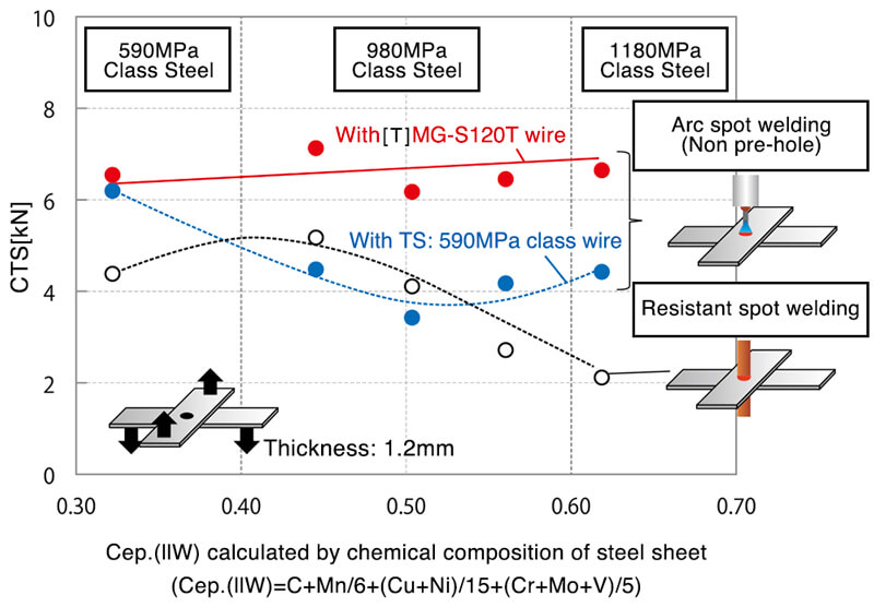
Figure 2: Influence of tensile strength of steel sheet, carbon equivalent,
welding method and consumable wire on cross tensile strength
3.Arc welding via wire feeding control
Wire feeding control has been drawing attention in thin steel sheet welding recently. This is a welding method in which the wire feeding direction is changed alternately forward and backward as shown in Figure 3.

Figure 3: Wire feeding control method
Utilizing both electric and mechanical control, this method allows welding heat input to be reduced in the welding of thin steel sheets, effectively resolving the issue of burn-through as well as reducing spatter. This method even reduces spatter even in the area of globular transfer generated by high welding current, compared with the conventional constant voltage welding method.
On the other hand, because the speed of the alternating forward and backward wire feeding is higher, wear on the contact tips increases drastically as well. Wear at the contact tip will lower the quality due to unstable electric conductivity and an unstable arc.
As a result, welding efficiency is reduced because additional contact tip wear means that tips must be changed frequently in order to maintain stability and quality of welding.
3-1. [F]MG-1T(F), solid wire for wire feeding control
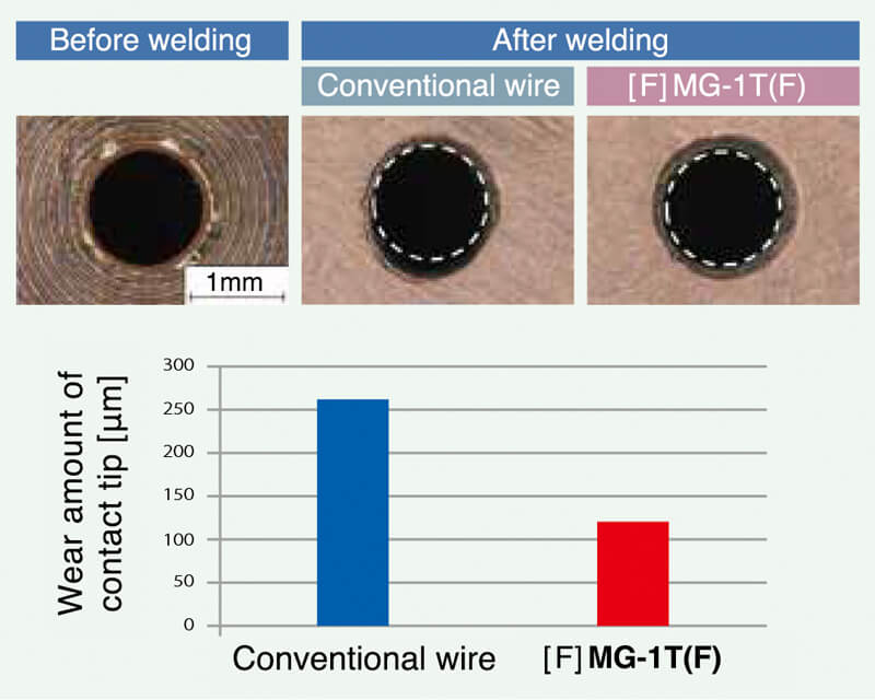
Figure 4: Comparison of wear at the contact tip
※One hour continuous welding at 200A-25V, 100%CO2 gas[F]MG-1T(F) features a special wire surface treatment that reduces wear of contact tips by decreasing abrasion between the solid wire and the contact tip and maintaining stable electric supply between them.
Figure 4 compares the difference in wear at the contact tips between a conventional solid wire and [F]MG-1T(F) after one hour of welding by the wire feeding control method.
It can be seen that using [F]MG-1T(F) wire resulted in about half the amount of wear at the contact tip compared with the conventional wire. In addition to reducing the wear of contact tips, the treatment improves wire feedability and arc stability as well.
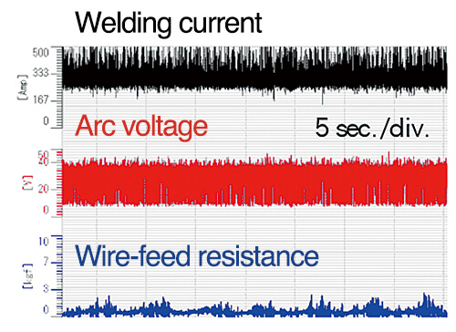
The test welding was conducted by using the wire feeding path shown in Figure 5, and the comparison result of time variation in the behavior on the tested welding current, arc voltage and wire feeding resistance between a conventional wire and [F]MG-1T(F) is shown in Figure 6. It was found that fluctuations in wire feeding resistance were limited.
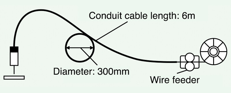
Figure 5: Schematic drawing of wire feeding test
| Conventional wire | [F]MG-1T(F) |
|---|---|
 |
![[F]MG-1T(F)](../../images/education-center/technical_hightlight/vol28_08.jpg) |
Figure 6: Time variation of welding current, arc voltage and wire feed resistance between a conventional wire and [F]MG-1T(F)
Table 1 shows an example of [F]MG-1T(F) with a chemical composition equivalent to JIS Z 3312 YGW12. Mechanical properties were evaluated by weld joints that were made according to JIS requirements, and those of the all-deposit metal are shown in Table 2.
| Wire | C | Si | Mn | P | S | Cu*1 |
|---|---|---|---|---|---|---|
| [F]MG-1T(F) | 0.05 | 0.89 | 1.40 | 0.006 | 0.015 | 0.24 |
| JIS Z 3312 YGW12 |
0.02-0.15 | 0.55-1.00 | 1.25-2.00 | ≤0.030 | ≤0.030 | ≤0.50 |
*1: Cu value contains Cu coating
| Wire | 0.2%OS (MPa) | TS (MPa) | El (%) | Absorbed energy at 0℃(J) |
|---|---|---|---|---|
| [F]MG-1T(F) | 420 | 530 | 29 | 110 |
| JIS Z 3312 YGW12 |
≥390 | 490-670 | ≥18 | ≥27 |
4.Properties required for automotive suspension components
As stated above in section 2, among all automotive parts, the suspension components in particular require a high grade of rigidity and fatigue strength. Accordingly, they comprise steel structures where the arc welding process is heavily utilized. Furthermore, high corrosion resistance is required of many of the suspension components as well because they are exposed to more corrosive elements than automotive body frames such as water that splashes during driving or the salt scattered on roads to prevent snow from freezing in cold regions.
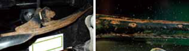
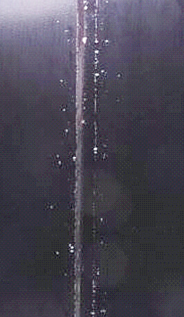
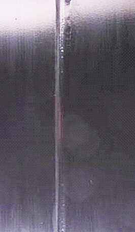
Figure 7: Rust generated on suspension components
and weld bead appearance
However, in arc welding, slag is generated during welding, which causes defects that impede the process of electro-deposition coating after welding. The outer appearance of a suspension component and its weld bead after actual running of a car are shown in Figure 7.
Rust is clearly seen near the locations of arc welding where coating defects were generated.
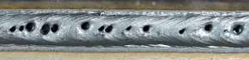
Figure 8: Porosity defects generated on a weld bead
Galvanization is regarded as a satisfactory means of improving the corrosion resistance of steel sheets; however, it is not appropriate for welded parts because welding heat causes the zinc coating to evaporate. Another drawback of galvanized steel sheets is bad weldability in that evaporated zinc gas is likely to remain in the weld metal, leading to the occurrence of porosity defects such as blow holes and/or pits as shown in Figure 8.
Therefore, while arc welding provides many of the properties required for suspension components, improvements in arc welding consumables and welding procedures are needed to avoid the drawbacks mentioned above.
4-1. New welding process with excellent corrosion and fatigue resistance
In order to solve the issues discussed above, a new welding process, called the Hi-Ar Process, was developed jointly between KOBE STEEL and Mazda Motor Corp. In this process, the conventional solid wire commonly used as a welding consumable for car production was re-designed to feature little slag generation and superb slag cohesiveness.
| Conv. Process |
 |
|---|---|
| Hi-Ar Process |
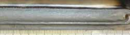 |
Figure 9: Comparison of bead appearance between
80%Ar-20%CO2 shielding gas
(conventional process)and Hi-Ar Process
Furthermore, the combination of 95%Ar-5%CO2 shielding gas containing a high Ar ratio with a conventional pulsed power source reduces slag generation while increasing porosity resistance on galvanized steel sheets. Figure 9 compares bead appearance produced by a conventional solid wire (equivalent to JIS Z 3312 YGW12) and the Metal Act ive Gas (MAG) welding proces swith 80%Ar-20%CO2 shielding gas (conventional process) and 95%Ar-5%CO2 shielding gas (Hi-Ar Process).
In contrast to the conventional process, which produced dotted slag on the bead, the Hi-Ar Process resulted in aggregated slag at the weld-end, a so called crater, which can minimize the places where electro-deposition coating defects can occur.
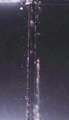
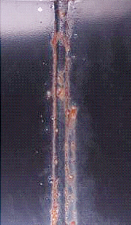
An evaluation of corrosion resistance after electro-deposition coating was performed in accordance with the combined cyclic corrosion test (CCT), and the results are shown in Figure 10.
| Before CCT |
CCT: 10cycle |
CCT: 30cycle |
|
|---|---|---|---|
| Conv. Process |
 |
 |
 |
| Hi-Ar Process |
 |
 |
 |
Figure 10: Comparison of corrosion resistance between conventional and Hi-Ar processes
Rust is generated at the CCT=10 cycle in the conventional process whereas it is not generated even at CCT=30 cycle in the Hi-Ar Process. Therefore, it is clear that the latter can provide superior corrosion resistance.
Another result of the Hi-Ar Process is that it improves fatigue strength of welded joints. An enlarged cross-sectional macrostructure of a weld toe is shown in Figure 11.
| Conv. Proces | Hi-Ar Process | ||
|---|---|---|---|
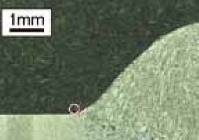 |
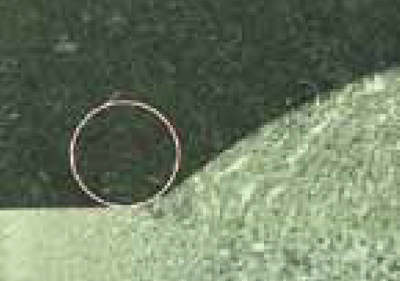 |
||
| Flank angle [deg] | 128 | Flank angle [deg] | 160 |
| Toe radius [mm] | 0.1 | Toe radius [mm] | 0.7 |
Figure 11: Comparison of toe shapes
Judging from the flank angle and toe radius of the weld toe configuration, the weld toe obtained by the Hi-Ar Process shows a smooth shape that is unlikely to cause stress concentration in comparison with that by the conventional process.
Figure 12 shows the result of the plane bending fatigue test on fillet welded lap joints of 440MPa class steel plates. The result by the Hi-Ar Process indicates improvement of about 1.5 times in load stress in 1.0 x 10⁷ in comparison with the conventional process.
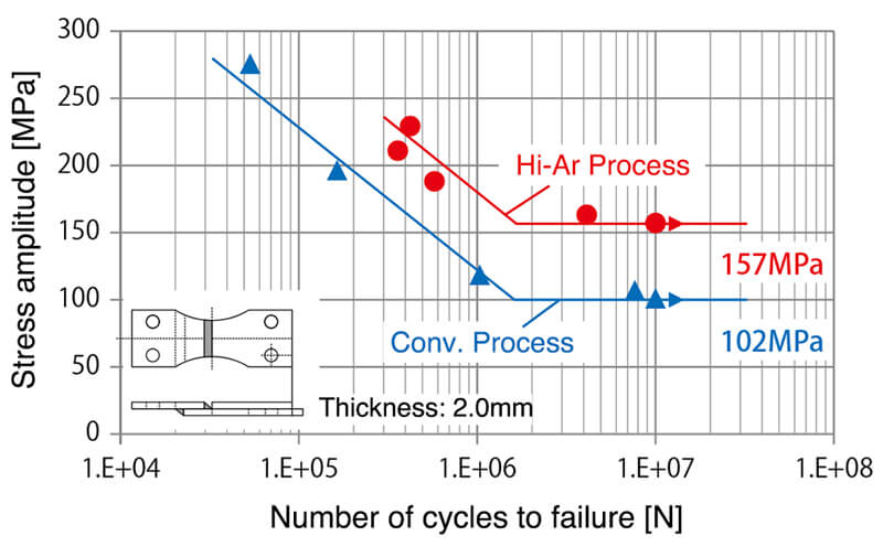
Figure 12: Results of fatigue test ※Stress ratio=0, Frequency=25Hz
4-2. Effectiveness of the Hi-Ar Process on actual parts
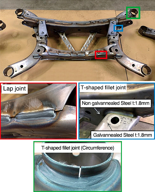
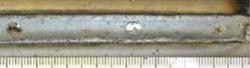
Figure 13: Appearance and welds of suspension cross-members
Actual welding on manufacturing lines can be problematic due to variations in the gaps between steel plates, tack welding accuracy and welding positions, and differs from the evaluations of corrosion and fatigue resistance reported on above. Therefore, an evaluation on actual suspension components for current mass-production vehicles was carried out. The appearance and welds of the suspension cross-members are shown in Figure 13.
In each specimen (a circumferential T-shaped fillet joint, T-shaped fillet joint and fillet welded lap joint), slag is aggregated at a crater, and a smooth bead was obtained. Therefore, the Hi-Ar Process is likely to be effective in welding actual parts and should improve corrosion resistance after electro-deposition coating.
5.Conclusion
The technologies discussed in this article were [T]MG-S120T, a solid wire for ultra-high tensile strength steel sheets; [F]MG-1T(F), a solid wire exclusively for welding thin steel sheets and suitable for controlling wire feeding in arc welding ; and also the newly-developed Hi-Ar Process, a solution that provides superior corrosion and fatigue resistance.
We expect that the products and the process described above will satisfy the needs of automakers and improve results for the welders who produce automotive parts.
However, as we believe that many issues remain to be resolved, we at KOBE STEEL will continue to develop original technology.
Products
- Main Products
- Welding Consumables
- Arc welding robots
- Industries - Recommended Materials
- Welding Handbook Quick View
- Product Quick View & Highlights
- For HEAT-RESISTANT STEEL
- For STAINLESS STEEL
- For LOW-TEMPERATURE STEEL
- Product Highlight
- Catalog
- Technical Highlights
- Certification
- SDS ※English Only
- ARCMAN
- Welding Robot
- Software


