

- Home >
- Products >
- Technical Highlight >
- Vol.29:Technology to prevent end cracking in one-side submerged arc welding
Technical Highlight Vol.29
Vol.29: Technology to prevent end cracking in one-side submerged arc welding

1.Preface
One-side submerged arc welding (SAW) is a highly efficient welding process that enables complete welding in one layer from one-side. KOBE STEEL has developed three one-side SAW processes: FCB™, RF™ and FAB, which differ in terms of backing materials/methods. All have been well utilized for butt joint welding of steel plates, in accordance with their respective features and merits in the shipbuilding and bridge construction fields.
Developed almost 50 years ago, all three processes have been in practical use ever since. However, one issue that has not yet been effectively resolved is solidification cracking at the end of welded joints (hereinafter called end cracking) during one-side SAW.
While a number of preventive methods have been developed, some of which remain in use, none of them can achieve both a high ratio of crack prevention and no repair-welding: therefore, a method that fundamentally solves the issue has long been sought in order to improve weld quality as well as boost operation efficiency.
In this article, the mechanisms of end cracking generation and the characteristics of conventional prevention methods will be discussed. The article goes on to report on the factors that are most effective in preventing end cracking, which were revealed through simulation analysis technology and then verified in actual welding.
2.Mechanisms of end cracking generation and conventional prevention methods
At the end of a weld joint, rapid deformation occurs on the steel plate right after the first (or leading) electrode (hereinafter called L electrode) reaches the run-off plate (or tab plate) as shown in Figure 1. End cracking can be generated when the tensile stress caused by deformation is added into the final solidification of the weld metal.
A schematic drawing of the conventional methods to prevent end cracking is shown in Figure 2, and their features are listed in Table 1.
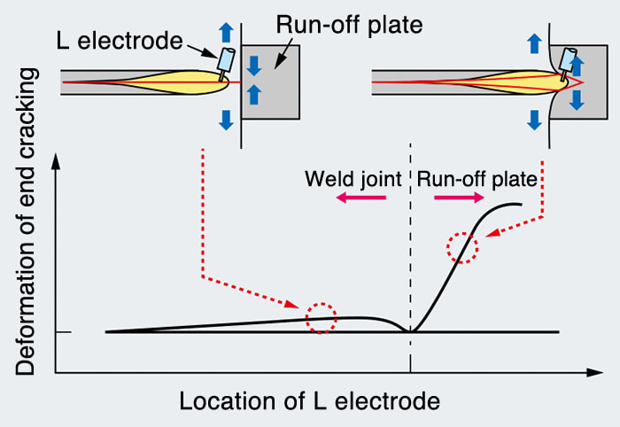
Figure 1: Outline of end cracking
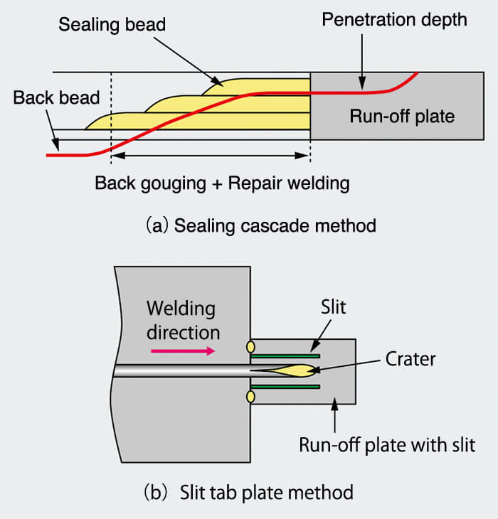
Figure 2: Schematic drawing of conventional methods
to prevent end cracking (a) and (b)
| Merit | Demerit | |
|---|---|---|
| Sealing cascade method | High prevention rate | Require repair welding |
| Slit tab plate method | High prevention rate in thin plates | Require a large run-off plate |
| Joining-crater method | High prevention rate | Require repair welding |
In the sealing cascade method (Figure 2 (a)), sealing beads are layered in at the end of the weld joint so as not to form a back bead but leave an unmelted binding bead, thus restraining deformation. It provides a high crack prevention rate; however, repair welding after one-side SAW is required.
In the slit-tab plate method (Figure 2 (b)), making slits on the run-off plate (i.e. using a slit-tab) restrains rapid deformation even when the arc of the L electrode reaches the run-off plate. However, while the end cracking prevention rate is high for thinner plates, it is low for thick plates, which require high heat input. In addition, how a tack weld bead is placed inside a groove can also lessen the effectiveness of this method.
Ultimately, both methods have merits and demerits but neither suffices as a technique that is excellent in end cracking prevention as well as welding efficiency.
3.Using FEM simulation to isolate the factors that restrain distortion
As steel plates available for welding under laboratory conditions tend to be small in size, the results of investigations into end cracking cannot necessarily be applied to actual work sizes. Therefore, in joint research with Osaka Prefecture University (OPU), the variables that restrain distortion generated at the end of weld joints were extracted by heat conduction analysis and thermal elastic-plastic analysis by means of the idealized explicit finite element method (FEM), a proprietary technology developed by OPU that is excellent in analysis of large-sized models.
According to heat conduction analysis, as shown in Figure 3, the idealized explicit FEM simulation obtained a penetration configuration similar to that of conventional actual welding as well as similar results for temperature increase and cooling rate at heat affected zones.
With thermal elastic-plastic analysis, several variables were evaluated utilizing plastic strain increment in the brittleness temperature range (BTR) during cooling (hereinafter called plastic strain increment in BTR) as an index of crack generation (see Figure 4). The result suggested that as the plastic strain increment in BTR was reduced by shortening the intervals between tack weld beads and using slower welding speeds (see Table 2), distortion at the end of a weld joint was restrained.
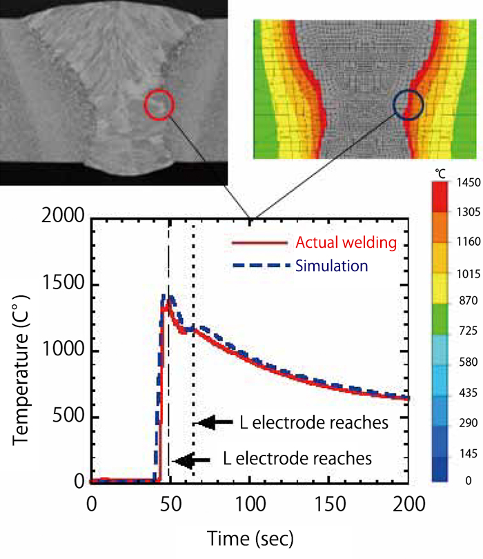
Figure 3: Example of heat conduction analysis by means
of idealized explicit FEM
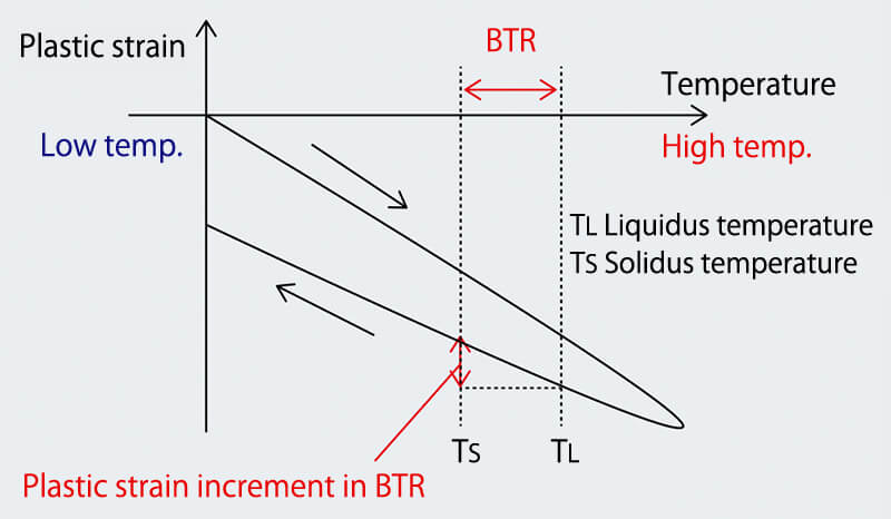
Figure 4: Model of solidification cracking generation
| Various factors | Plastic strain increment in BTR | |
|---|---|---|
| Large | Small | |
| Interval of tack weld beads | Long→Short | |
| Welding speed | Fast→Slow | |
| Width of a run-off plate | Narrow→Wide | |
| Connection between work piece and run-off plate |
Weak→Strong | |
| Width of steel plates to be welded |
Narrow→Wide | |
| Length of steel plates to be welded |
No influence * | |
4.Verification of simulation results by actual welding
4-1. Test method
The verification of variables isolated via simulation was performed by measuring displacement and carrying out non-destructive test (NDT) at the end of a weld joint obtained by actual welding. The welding process and tested consumables are shown in Table 3.
| Welding process | FCB™ one-side SAW with three (L, T1 and T2) electrodes |
|
|---|---|---|
| Welding consumables |
Welding wire | [F]US-36 |
| Flux | [F]PF-I55E | |
| Backing flux | [F]PF-I50R | |
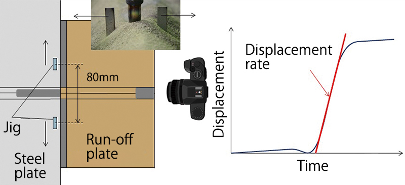
Figure 5: Method of measuring the displacement rate at the
end of a weld joint
As shown in Figure 5, a moving jig placed in the vertical position against the welding line during welding allowed for taking moving image photography, which was then used to measure displacement at the end of the weld.
The obtained displacement was plotted along the time axis. The incline was defined as the displacement rate, providing an index of crack generation. Weld specimens were tested to determine the existence of crack by radiographic examination within a range of 700 mm from the extreme end of a weld joint, using Japanese Industrial Standard (JIS) Z 3104 (1995): Methods of radiographic examination for welded joints in steel.
4-2. Effects of different factors in restraining the displacement rate
The results of actual welding accorded with those of the simulation on the effects listed in Table 4, confirming further that these variables can bring about a lower displacement rate of the end of a weld joint during welding.
| Variables | Simulation | Actual welding | |
|---|---|---|---|
| Plastic strain increment in BTR |
Displacement rate |
||
| Interval of tack weld | Long→Short | ||
| Welding speed | Fast→ Slow | ||
| Width of run-off plate | Narrow→Wide | ||
| Connection between work piece and run-off plate |
Weak→Strong | ||
| Width of steel plates to be welded |
Narrow→Wide | ||
| Length of steel plates to be welded | No influence * | - | |
Figure 6 shows the verified results of welding a 20mm thick plate and testing such variables as the intervals between tack weld beads, welding speed and the width of run-off plates.
It was found that the displacement rate could be decreased by placing sealing beads instead of tack welding beads at the end of a weld joint, adopting low welding speed, and setting a wider run-off plate, respectively.
On the other hand, as shown in Figure 7, some of the welded joints showed end cracking despite a small displacement rate and the application of low speed welding.
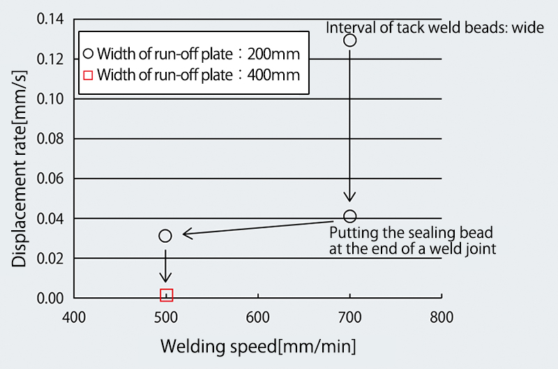
Figure 6: Relationship between
variables and displacement rate
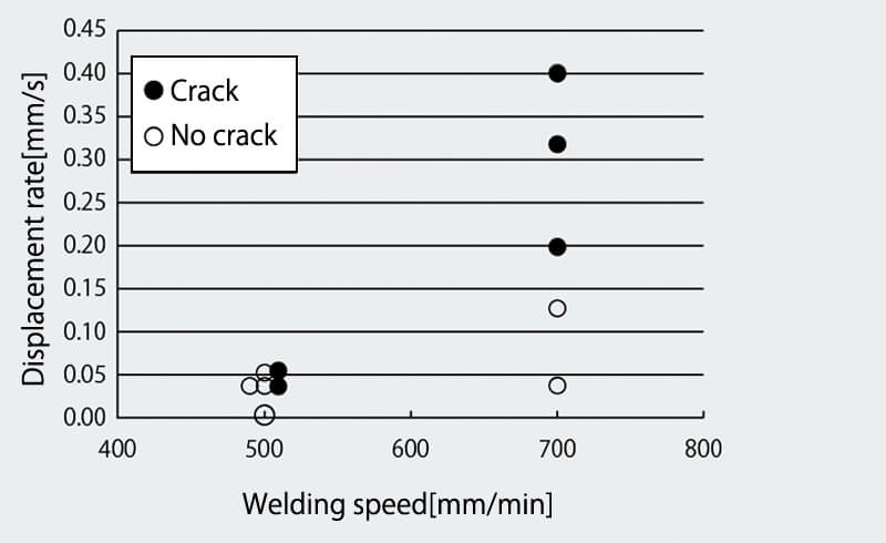
Figure 7: Crack or no crack found under low
welding speed condition
4-3. Control of solidification microstructure
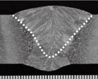
In order to understand the disparity above, the solidification microstructures of instances in which end cracking occurred under low welding speed condition were compared with the instances in which no end cracking occurred but welding was carried out under standard conditions (see Table 5).
| Welding condition | Standard | Low speed |
|---|---|---|
| Cross-sectional microstructure |
 |
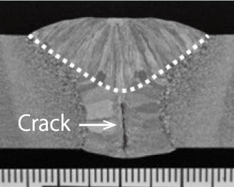 |
| Displacement rate (mm/s) |
0.13 | 0.04 |
It was confirmed that under the low welding speed condition, the solidification of the weld metal at the root grew out in a horizontal direction from both sides; in other words, it showed a solidification microstructure that can easily generate crack. Because it is necessary to keep the same heat input on each corresponding electrode under both low welding speed and standard conditions, a low welding current must be applied to each electrode under the low speed welding condition.
However, a low welding current applied to the third (or second trailing) electrode (hereinafter called T2 electrode) under low speed welding condition caused shallow penetration as well as a temperature drop in the weld metals formed by both the L electrode and the second (or first trailing) electrode (hereinafter called T1 electrode). The penetration of the T2 electrode can be easily increased by raising its welding current; however, the corresponding heat input increase can lead to an increase in the displacement rate. Therefore, adjusting the distance between the T1 and T2 electrodes was selected as an effective countermeasure.
Table 6 shows the relationship between the distance of T1 and T2 electrodes and the solidification microstructure under low welding speed condition.
| Distance of the second and the third electrodes (mm) | ||
|---|---|---|
| 120(standard) | 100 | 80 |
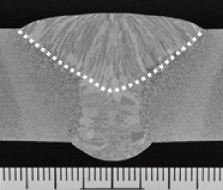 |
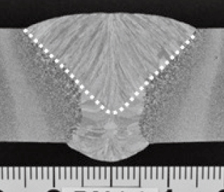 |
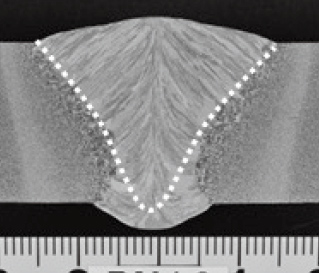 |
It was found that the solidification microstructure at the root could be improved by adjusting the distance between the T1 and T2 electrodes. Therefore, in order to control the solidification microstructure, it is important to choose an optimum distance that corresponds to the welding speed.
4-4. Influence of plate thickness
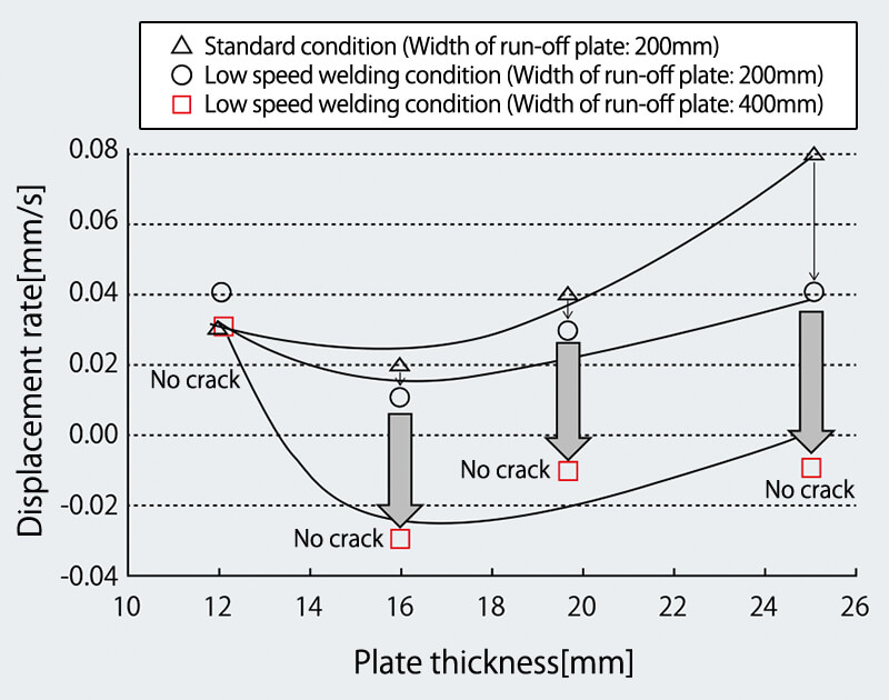
Figure 8: Relationship between plate thickness and
displacement rate
The influence of plate thickness on the displacement rate and end cracking was investigated on steel plates with thicknesses of 12, 16, 20 and 25 millimeters. In order to isolate this particular variable, welding was carried out after applying sealing beads, strengthening the connection between the run-off plate and the actual work piece and optimizing the low welding speed condition and the distance of T1 and T2 electrodes. The results are shown in Figure 8.
It can be seen that under the low speed welding condition, the displacement rate was significantly lower in all cases except for the 12 mm thick plate. In addition, end cracking did not occur in steel plates of any thickness.
5.Development of equipment with functions installed to prevent end cracking
Because end cracking occurs only at the end of weld joints, it is there where low welding speeds are required; indeed, standard welding conditions should be applied at the start and middle sections of the weld. However, In order to realize this, functions to automatically change welding conditions as well as the distance of T1 and T2 electrodes must be installed.
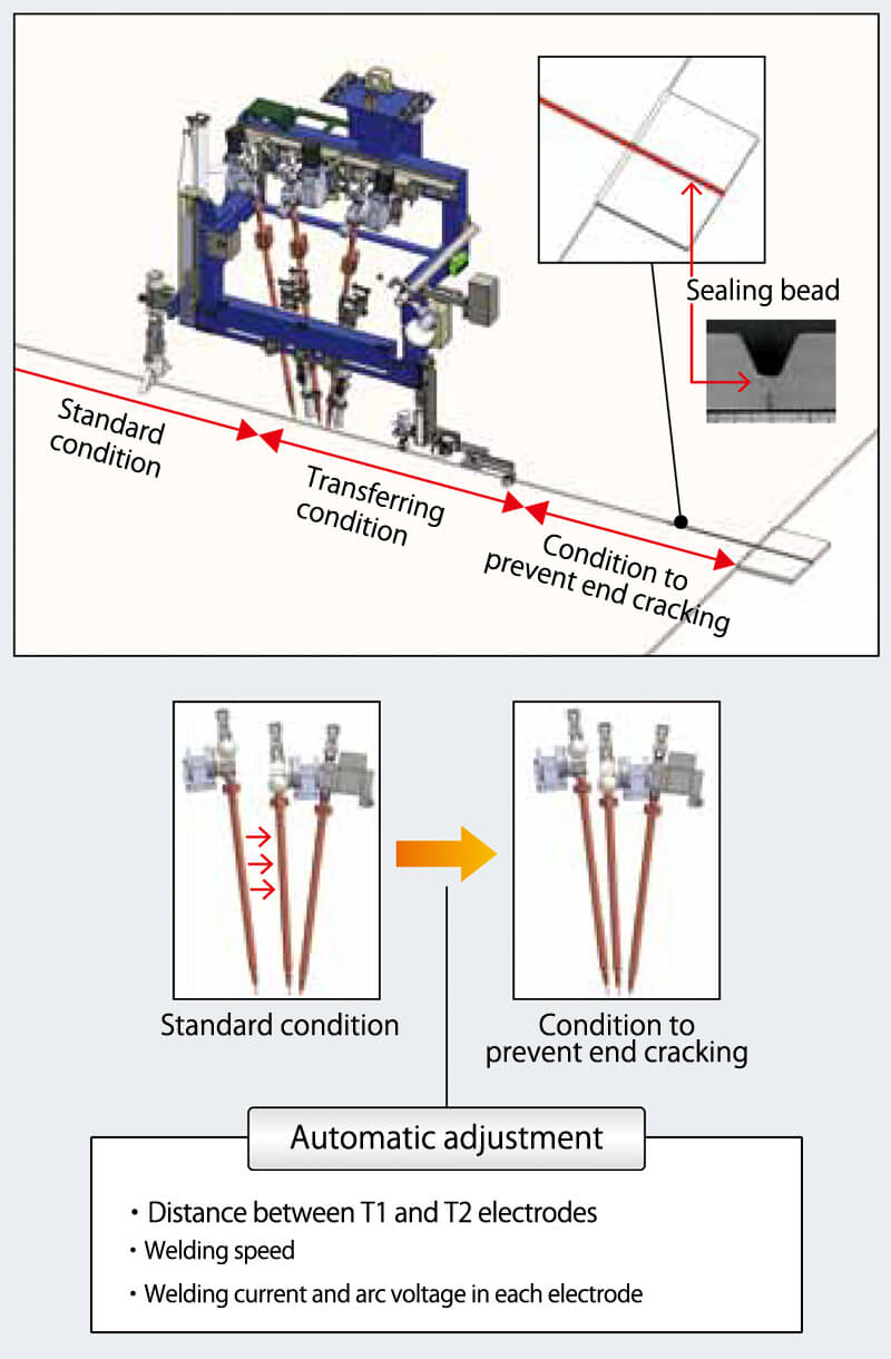
Figure 9: Schematic diagram of one-side SAW process
and equipment with functions installed
to prevent end cracking
As an abrupt change in welding conditions can affect the quality of welds, a transfer zone should be set for adjusting to the condition that prevents end cracking, as shown in Figure 9. Specifically, once the end zone of a steel plate is detected, the welding current, arc voltage and welding speed must be gradually adjusted within the designated transfer zone, and, simultaneously, the T1 and T2 electrodes are shifted to a set distance so that welding throughout the end part of the weld joint is performed under the low speed welding condition.
Testing has confirmed that the mechanical properties of weld metals within both the transfer zone and the end zone of the plate are equivalent to those formed under conventional standard welding conditions. The welding equipment with the necessary functions installed has already been developed and is ready to be evaluated in actual welding.
6.Postscript
From the results obtained through testings and investigation, end cracking may be prevented on plates up to 25 mm thick without repair welding by adopting the following:
①Setting sealing beads at the end of a weld joint
②Increasing the width of the run-off plate and strengthening the connection between the run-off plate and the work piece.
③Adopting low welding speed
④Controlling the solidification microstructure by adjusting the distance between the T1 and T2 electrodes
Because this technology is expected to contribute greatly to improving weld quality and productivity, it will be evaluated and verified further in welding of actual work pieces and put into practical use in the very near future.
Reported by
Masaharu. Komura,
Welding System Department, Technical Center, Welding Business
1. H. Yokota; End cracking; Welding Technical Guide,KOBE STEEL, LTD. 2018, Vol. 497, p.19
2. K. Tanaka; End cracking in Submerged Arc Welding;Welding Technical Guide, KOBE STEEL, LTD. 1997,Vol. 37, No. 329, p.1-7
3. M. Shibahara et al; Computational Method for Transient Welding Deformation and Stress for Large Scale Structure Based on Dynamic Explicit FEM; The Quarterly Journal of the Japan Welding Society 2011, Vol. 29, No. 1, p.1-9
4. M. Shibahara et al; Effect of Various Factors on Solidification Crack under FCB Welding; The Welding Structure Symposium 2014,p247-254
5. H. Yokota et al; The Japan Welding Society, National Convention Lecture 2017-9 Vol. 101 p.90-91
Products
- Main Products
- Welding Consumables
- Arc welding robots
- Industries - Recommended Materials
- Welding Handbook Quick View
- Product Quick View & Highlights
- For HEAT-RESISTANT STEEL
- For STAINLESS STEEL
- For LOW-TEMPERATURE STEEL
- Product Highlight
- Catalog
- Technical Highlights
- Certification
- SDS ※English Only
- ARCMAN
- Welding Robot
- Software


