

- Home >
- Products >
- Technical Highlight >
- Vol.30:A new function for the ARCMAN™ robotic welding system: root gap detection by laser sensor
Technical Highlight Vol.30
Vol.30: A new function for the ARCMAN™ robotic welding system: root gap detection by laser sensor

1.Preface
KOBE STEEL’s ARCMAN™ robotic welding systems are used by many customers in the building construction and construction machinery fields, which fabricate structural steels from middle to heavy plate thickness as shown in Figures 1 and 2. One of the advantages of robotic systems is to increase production efficiency. However, in order to achieve this in welding, it is essential to shorten tact time while maintaining welding quality. A robot simply performs whatever an operator teaches; however, depending on the accuracy of the workpieces and/or grooves, cases may occur in which a robot cannot perform precise welding under a set welding condition. Welding defects may result because large structures that employ plates of middle and heavy thickness can generate distortion and/or assembly errors. As a result, repair is required at the post-process stage, and overall production efficiency drops. During welding, welders keep their eyes on the workpiece shape and/or root gap and adjust their welding accordingly. To conduct high quality welding with a robot, then, it would seem necessary to provide the robot with eyes.
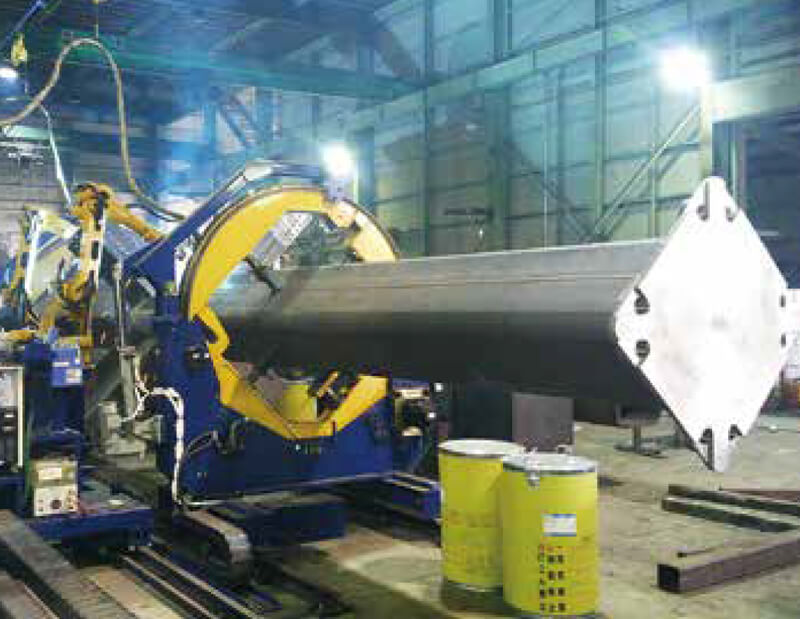
Figure 1: ARCMAN™ structural steel large
assembly “2-arc” robotic welding system
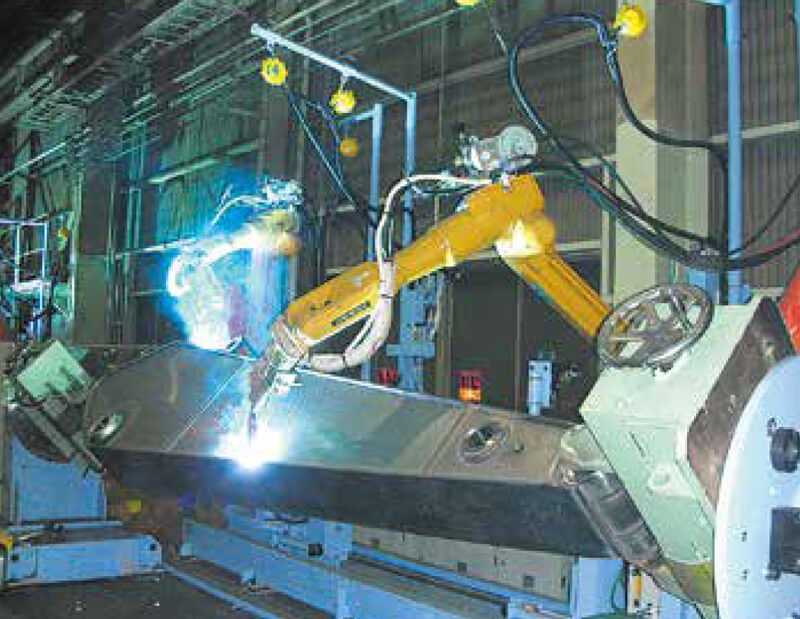
Figure 2: ARCMAN™ robot welding system for arm of
construction machinery
Currently, touch sensing offers the alternative to actually fitting a robot with eyes. It allows a workpiece position to be detected by utilizing the voltage applied to a welding wire that changes once the wire touches the workpiece. However, touch sensing is known to have weaknesses such as accuracy, the inability to function with certain groove shapes, and sensing movements that take more time than planned. In order to overcome these weaknesses, KOBE STEEL has developed a new system based on root-gap detection utilizing the company’s exclusive CB-Type Controller and a laser sensor. In this article, the features and actual usage of a laser sensing function will be discussed.
2.Outline of the laser sensor
2-1. Advantage of the laser sensor
There are three advantages when a laser sensor is applied for the robotic welding system.
① Wide range of joints
As shown in Figure 3, root gap detection has been applied not only to the conventional single-V and single-bevel grooves but also to the flare groove and T joint that could not be covered by the touch sensing method.
② Highly accurate measurement
Because the maximum measurement resolving power of the laser is 0.1mm or less, highly accurate measurement is possible, depending on the condition of measurement and workpiece.
③ Reduction of cycle time
Because the action of irradiating against a groove and measuring the root gap with the linear laser beam needs to occur only one time, the sensing cycle time is shortened. By contrast, the touch sensing method as shown in Figure 4, requires repeated operations for detecting the workpiece and measuring the root gap.
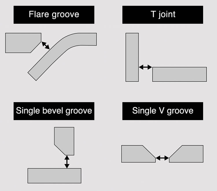
Figure 3: Groove shapes applicable to detection by laser
sensing
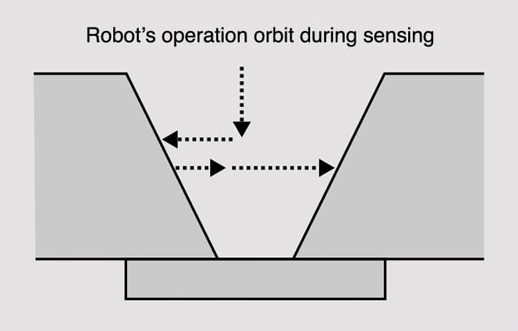
Figure 4: Root gap measurement by touch sensing
method
The robot’s operation orbit varies, depending on measuring and workpiece conditions.
2-2. Disadvantages associated with laser sensing
Despite the advantages of applying the laser sensor to the robotic welding system, some problematic issues have held back the adoption of laser sensing systems.
① Decreased operation ratio
Because the laser sensor must be placed close to the welding torch so that the laser sensor can additionally be mounted onto welding systems, the robot’s operation ratio may drop due to the laser sensor’s possible interference with workpieces.
② Necessity of safety measures
The installation and use of laser equipment require particular safety measures in accordance with standards by laser classification, because of the need to protect human bodies against harmful exposure to laser beams.
③ Influence of workpiece condition
As measurement is performed by reflecting the laser beam against a workpiece, the surface condition of the workpiece and/or any imperfections may have a large influence on the results.
2-3. A solution to laser sensing’s disadvantages
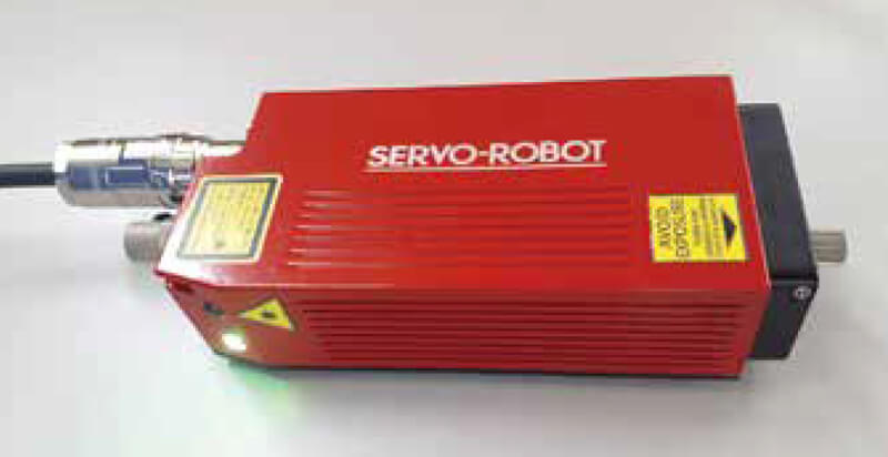
Figure 5: The custom-made SFK350 Laser Sensor
In order to resolve the issues raised above, KOBE STEEL has partnered with SERVO-ROBOT INC to offer the SFK350 laser sensor, which is custom-made and specially designed for the ARCMAN™ robotic welding systems. How the SFK350 (see Figure 5) improves the productivity of laser sensors is discussed below.
① Slim body allows the SFK350 to be used in confined spaces.
Table 1 compares the size of the custom-made SFK350 with that of the conventional laser sensor. It is clearly seen that the SFK350 has been reduced in size by about 50 % and weight by about 10 %; thus, the drop of operation ratio is surely restrained.
| SFK350 | Conventional laser sensor |
|
|---|---|---|
| Cubic volume (cm3) | 368 | 749 |
| Weight(g) | 600 | 670 |
② Laser classification is less restrictive
According to the Safety of Laser Products (JIS C 6802: 2018), the conventional sensor is classified as Laser Class 3B, which requires isolation of the operating environment; however, the custom-made SFK350 is classified as Laser Class 2M, which does not, thereby allowing the system to be applied more widely.
Table 2 displays an excerpt from Hazards and Preventive Measures against Damages Caused by Laser Beam, provided by the Head of Standards Bureau of the Ministry of Health, Labor and Welfare (Japan) for reference.
| Class 2M | Class 3B | |
|---|---|---|
| Protective equipment ・Safety glasses ・Working clothes with little exposure of skin |
Not required | Required |
| Peripheral isolation | Not required | Required |
| Designated laser-controlled area | Not required | Required |
| Designated laser safety officer | Not required | Required |
Because the conventional laser sensor has a strong output laser beam, it is classified as Laser Class 3B, and a number of hazard prevention measures are required. In addition to peripheral isolation, wearing protective equipment, and setting a designated laser-controlled area as well as a laser safety officer are required.
The specifications of SFK350 are listed in Table 3. A laser sensor with seam-finding function for detecting root gaps, it is enclosed in a strong casing that can tolerate any welding environment. Moreover, the algorithm that measures workpieces fabricated from steel plates of middle to heavy thickness steel plates that KOBE STEEL is known for is programmed in every groove configuration.
| SFK350 | |
|---|---|
| Laser classification | Class 2M |
| Type of measurement | Seam-finding |
| Dimension (width x height x depth) | 63mm x 139mm x 42mm |
| Depth of field | 350mm |
| Stand off | 200mm |
| Close plane (Field of view) | 39mm |
| Far plane (Field of view) | 111mm |
| Lateral resolution | 0.07mm (@350mm) |
| Depth resolution | 0.48mm (@350mm) |
③ Reduction of influence on workpiece surface condition
In laser sensing, scanning is conducted to reduce the influence of the surface condition of the workpiece. Adhesions from welding fume or spatter to the surface of the workpiece or the inside of the groove, or even the scars left from processing or assembly, can change the apparent groove shape in a particular spot, resulting in incorrect measurements when one point only is measured by the laser sensor.
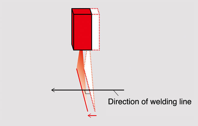
Figure 6: Laser sensor scanning operation
For these reasons (as shown in Figure 6), the laser sensor first scans a certain distance along the direction of the welding line in order to obtain measuring data, which are then averaged, thereby reducing the possibility of using incorrect measurements.
2-4. Comparison of laser sensing with touch sensing
Table 4 shows a comparison between laser sensing and touch sensing. Because both sensing methods have advantages and disadvantages, it is necessary to determine first whether the use of the laser sensor is applicable to a particular target workpiece.
| Laser Sensing | Touch Sensing | |
|---|---|---|
| Applicable joint | Many | Few |
| Measurement resolving power | 0.1 mm or less | About 0.5 mm |
| Sensing time | About 1 sec.(scanning time) | About 10 sec.(detection time) |
| Influence on operation ratio | Yes | No |
| Influence of surface condition | Influenced by reflection | Influenced by non-conductive parts |
| Influence from disturbance | Direct sunlight Arc light | No |
| Accuracy (i.e. difference in sizes and processing conditions between the workpiece and drawing) | Necessary for adding the sizes and measurement of the workpiece based on processing conditions. | The same setting can be applied even if there is some extent of dispersion. |
| Cost | High | Low |
Note: Blue text indicates advantages.
3.System components
The laser sensing system is composed of a laser sensor, the ARCMAN™ robot and CB controller, shown in Figure 7.
When laser sensing is carried out, groove information on the target workpiece is sent from the CB controller to the laser sensor, and then sensing is conducted by means of an algorithm based on the groove information. The CB controller acquires the results measured by the laser sensor such as the distance up to the groove center, the root gap (or gap width) and other characteristics of the target groove. The accumulated information is displayed as laser sensing results on the screen of the teaching pendant as shown in Figure 8.
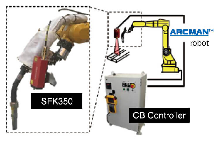
Figure 7: Laser Sensing System components
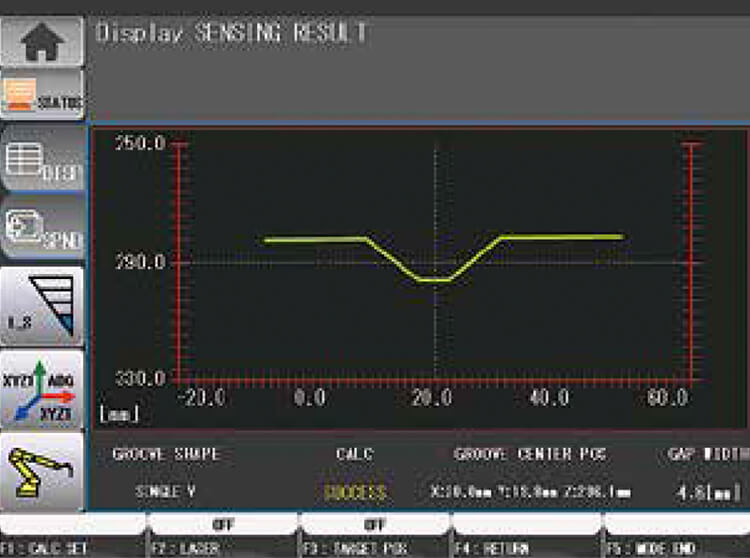
Figure 8: Screen of laser sensing result display
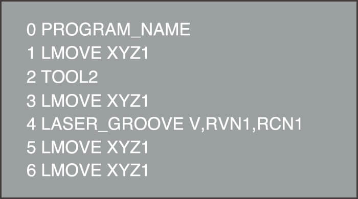
Figure 9: Laser sensing teaching program
The teaching program is made by utilizing the exclusively programmed command for laser sensing (see Figure 9). It should be noted that laser sensing is composed of three treatments (or functions): laser radiation, measurement and acquisition of results. Although it is possible to use more than one command in combination with the versatile command for each function, it is also possible to carry out laser sensing by executing the one exclusively programmed command.
The detailed contents fall under three points as follows:
① Groove configuration or algorithm number to measure
② Storage location of correction amount measured by laser sensor
③ Storage location of root gap measured by laser sensor
The root gap detection function in combination with measured root gap and robotic functions enable welding under the welding condition adjusted to the measured root gap. Details of the teaching method are provided in the SFK350’s laser sensing operation manual.
4.Contribution to higher quality welding
An important contribution to high quality welding is the gap sensing function, which automatically adjusts welding conditions according to the measured results of root gaps that vary in size in the groove. Changes in the root gap must be measured in advance of the welding of a workpiece.
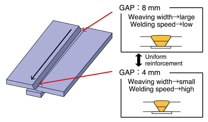
Figure 10: Root gap sensing function
Figure 10 shows a root gap with a tapered shape in a groove that changes from 8 mm to 4 mm. In this case, teaching would be programmed with the 4 mm root gap.
Even though the root gap on the actual workpiece differs from that of the teaching workpiece, the weaving width as well as the welding speed is automatically adjusted to provide uniform reinforcement of the bead.
5.Postscript
This report discussed the laser sensor’ s root gap detection function, which allows robotic welding systems to carry out higher quality welding. Specifically, the article examined some of the differences between laser sensing and touch sensing, and their respective features and discussed examples of actual application.
As the basis of developing this function, the following two functions are added:
① Exclusively programmed command for laser sensing
② Screen to display sensing results
These functions provide easier operation of the ARCMAN™ robotic welding systems that have a laser sensor installed.
KOBE STEEL will continue developing such products so that all of our customers will experience complete satisfaction with robot welding.
1. JIS C 6802: 2018, Safety of Laser Products;
Japanese Industrial Standard (February, 2005)
2. Notification from the Head of Standards Bureau of Ministry of Health, Labor and Welfare, No. 0325002 (March 25, 2005)
3. Operation Manual of Laser Sensing Function (for SFK350) Chapter 2, Column 1 Teaching Method of Root Gap Detection Command, KOBE STEEL, LTD.
Products
- Main Products
- Welding Consumables
- Arc welding robots
- Industries - Recommended Materials
- Welding Handbook Quick View
- Product Quick View & Highlights
- For HEAT-RESISTANT STEEL
- For STAINLESS STEEL
- For LOW-TEMPERATURE STEEL
- Product Highlight
- Catalog
- Technical Highlights
- Certification
- SDS ※English Only
- ARCMAN
- Welding Robot
- Software


