

- Home >
- Products >
- Technical Highlight >
- Vol.32:The new SAW FAMILIARC™ US-29HK /TRUSTARC™ PF-H55LT-N,for Offshore Wind Power Generators
Technical Highlight Vol.32
Vol.32: The new SAW FAMILIARC™ US-29HK /TRUSTARC™ PF-H55LT-N,for Offshore Wind Power Generators

1.Preface
Submerged arc welding (SAW) is a common arc welding process, and in Japan about 11% of welding consumables are applied to SAW. It is mostly used for long straight welding lines in the fields of steel tubes and pipes, steel frames and bridges, shipbuilding and chemical engineering/machines.
As for SAW consumables, just three industries account for more than half of total consumption: steel tubing and piping, steel structure/bridge construction and shipbuilding. However, among those three, the steel structure/bridge construction and shipbuilding industries account for a higher share of SAW consumption than the steel tubing/piping industry.
Since 2000, interest in alternative methods of power generation that feature reduced CO2 emissions has steadily grown worldwide in response to environmental issues such as global warming. For example, many countries have accelerated the introduction of power generators that utilize renewable wind power and solar energy. Especially in Europe, where conditions for wind power are excellent, installation of wind power generators has been widespread; moreover, large size generators that further increase the electrical generation capacity of off-shore wind power generators have recently drawn attention.
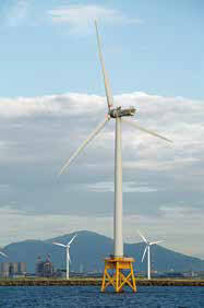
Many off-shore wind power generators are supported by a mono pile, a large-sized steel cylinder driven deep into the sea bed that serves as the foundation for the tower and windmill. On these pipes, the highly efficient SAW process is mainly applied, especially the SAW methodutilizinga narrow groove, which is both highly efficient and labor saving.
KOBELCO now offers the newly-developed combination of [F]US-29HK wire and [T]PF-H55LT-N flux as the SAW consumables most suitable for narrow groove, seam welding and/or circumferential welding of steel tubes and pipes as well as for low temperature service.
2.Properties of the [F]US-29HK wire and [T]PF-H55LT-N flux combination
As shown in Table 1, the SAW flux [T]PF-H55LT-N is a fluoride-basic type of bonded flux and has excellent usability even in a narrow groove due to its superb optimization of flux components. In combination with the SAW wire [F]US-29HK, it provides extremely stable notch toughness down to -60 ℃ and is applicable to both alternating current (AC) and direct current, electrode positive (DCEP). It is also recommended to use in the as-welded condition.
| Flux type of [T]PF-H55LT-N | Fluoride-basic type |
|---|---|
| Electrode-Flux classification | AWS A5.23 F8A8-EH12K |
| Applicable base metal grade |
・Up to YP460 MPa grade steel (e.g.:DNV F460) |
| Features |
・Excellent slag removal, bead shape and good resistance of various welding defect for narrow groove ・High strength(up to YP460 MPa) and excellent impact value at low temperature down to -60℃ ・Applicable for DCEP and AC polarity |
Note. DNV: Det Norske Veritas
2-1. Properties of the deposited metal
Tables 2 and 3 show the chemical composition and the mechanical properties in the as-welded condition by both DCEP and AC, based on AWS requirements. Figure 1 exhibits the notch toughness property in the as-welded condition and Figure 2, bead appearance.
The diffusible hydrogen content of the deposited metal welded by the combination of [F]US-29HK / [T]PF-H55LT-N with DCEP is shown in Table 4. It indicates an extremely low level of about 3 mL/100 g, below H5.
| Polarity | C | Si | Mn | P | S | |
|---|---|---|---|---|---|---|
| [F]US-29HK / [T]PF-H55LT-N | DCEP | 0.07 | 0.29 | 1.85 | 0.013 | 0.002 |
| AC | 0.08 | 0.27 | 1.73 | 0.013 | 0.002 |
Note. Welding condition: 550 A-30 V-42 cpm; Ext.=30 mm; 4.0 mm wire dia.
| PWHT condition | Polarity | 0.2%OS (MPa) |
TS (MPa) |
El (%) |
|
|---|---|---|---|---|---|
| [F]US-29HK / [T]PF-H55LT-N | As-welded | DCEP | 514 | 603 | 28 |
| AC | 534 | 618 | 29 | ||
| AWS Specification (As-welded only) | Min 469 | 552-690 | Min 22 | ||
Note. Welding condition: 550 A-30 V-42 cpm; Ext.=30 mm; 4.0 mm wire dia.
| Polarity | Diffusible hydrogen content (mL/100g) |
Classification of shipping approval |
||||
|---|---|---|---|---|---|---|
| N-1 | N-2 | N-3 | Avg. | |||
| [F]US-29HK / [T]PF-H55LT-N | DCEP | 3.2 | 3.3 | 3.3 | 3.3 | H5 |
Note. *1. Welding condition: 500 A-30 V-40 cpm; Ext.=30 mm; 4.0 mm wire dia.
*2. Test method: According to JIS Z 3118 (Gas chromatography), equivalent to AWS A4.3 Standards Methods for Determination of the Diffusible Hydrogen Content of Martensitic, Bainitic, and Ferritic Steel Weld Metal Produced by Arc Welding.
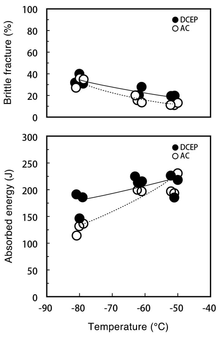
Figure 1: Transition curve of notch toughness
in the as welded condition
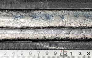
Figure 2: Bead appearance
2-2. Both side butt joint welding test in a narrow groove
A both side butt joint welding test in a narrow groove was performed with the combination of [F]US-29HK / [T]PF-H55LT-N under the welding condition and welding parameters shown in Tables 5 and 6, respectively. In this test, the base metal was an 80 mm thick steel plate with a 60° V-groove on the first side, a 40° V-groove on the second side, and a 10 mm root face in-between, as shown in Figure 4. The first side was welded in 8 passes. After the welding, the second side was machined into a U-shaped (8 mm radius), 16° groove to a depth of 58 mm from the second side surface, as shown in Figure 5. The second side welding was carried out in 21 passes by the tandem welding process: a 4.0 mm dia. wire for the leading electrode (DCEP) and two 2.4 mm dia. wires for the trailing electrodes (AC) in order to increase the deposition rate, as shown in Figure 3. The two trailing electrodes were connected to one power source only but through two contact tips.
In actual welding, however, a different welding procedure to the one above, including edge preparation, can be applied. For the first side welding, a single Ygroove can be prepared instead of a double V-groove, and after the first side welding, the U-shape groove can be machined. Both applications are recommended.
Regarding the actual application of the trailing electrode, while the method of two wires going through one contact tip was adopted, the method of two wires going through two respective contact tips with one power source is recommended. When two wires are used in one contact tip, a problem like a welding wire adhering to a contact tip will require the whole special contact tip to be changed, increasing down time for the operator, as well as the consumption of special contact tips.
Tables 5 and 6 show the test condition and the welding parameters. Figure 3, 4 and 5 also exhibit the location of electrodes at tandem welding and the pass sequences in both the first and second side grooves, respectively.
| Electrode | [F]US-29HK Leading electrode (L): 4.0 mm dia. Trailing electrode (T): 2.4 mm dia. x 2 wires |
|---|---|
| Flux | [T]PF-H55LT-N |
| Base metal | JIS G 3106 SM490A, 80 mm thick |
| No. of passes |
Welding parameter | Heat Input (kJ/mm) |
Preheat and interpass temperature |
|
|---|---|---|---|---|
| 1st side | 1 | Single, DCEP, 600 A-30 V-600 mm/min |
1.8 | 100-147 ℃ |
| 2 | Single, DCEP, 650 A-30 V-600 mm/min |
2.0 | ||
| 3-8 | Tandem, L: DCEP, 650 A-30 V T: AC, 600 A-32 V-700 mm/min |
3.3 | ||
| 2nd side | 1 | Single, DCEP, 600 A-30 V-600 mm/min |
1.8 | |
| 2-21 | Tandem, L: DCEP, 650 A-30 V T: AC, 600 A-32 V-700 mm/min |
3.3 |
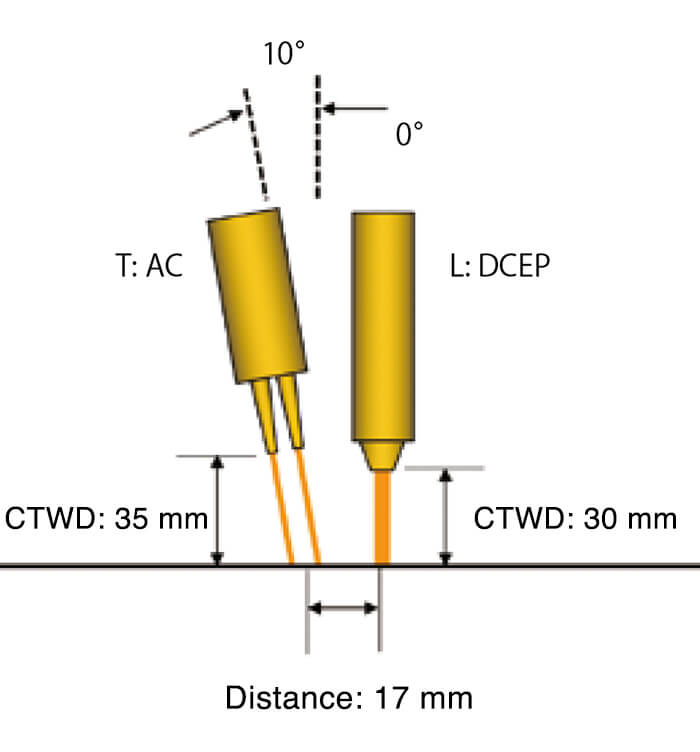
Figure 3: Location of electrodes at tandem welding
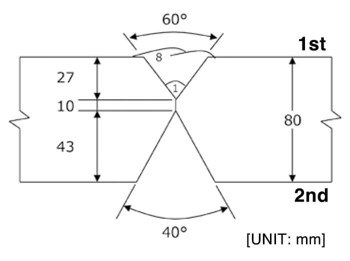
Figure 4: Groove configuration and pass sequences for the
1st side welding
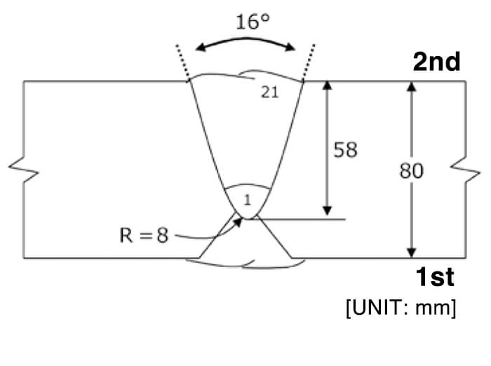
Figure 5: Groove configuration and pass sequences for the
2nd side welding
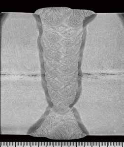
Figure 6: Macroscopic section
of both side butt joint welding
In welding this butt joint, excellent results were obtained. Figure 6 shows a macroscopic section and Tables 7 and 8, the chemical compositions and mechanical properties of the butt joint weld metal, respectively.
Overall, the properties of the welded butt joint can be evaluated as excellent, due to maintenance of high strength, the securing of sufficient notch toughness at -60 ℃, and the transition temperature being held below -60 ℃.
| C | Si | Mn | P | S |
|---|---|---|---|---|
| 0.09 | 0.30 | 1.78 | 0.014 | 0.003 |
Note. Location of chemical test specimen: Center of plate thickness
| PWHT condition |
Location of specimen |
0.2%OS (MPa) |
TS (MPa) |
El (%) |
vE-60℃ (J) |
vE-40℃ (J) |
||
|---|---|---|---|---|---|---|---|---|
| As-welded | 7 mm beneath the surface on the 2nd side |
496 | 618 | 33 | 112 123 127 |
Avg. 121 | 161 156 147 |
Avg. 155 |
| 40 mm beneath the surface on the 2nd side |
580 | 634 | 28 | 162 181 152 |
Avg. 165 | 194 196 196 |
Avg. 195 | |
| 73 mm beneath the surface on the 2nd side |
591 | 664 | 28 | 128 130 179 |
Avg. 146 | 184 185 183 |
Avg. 184 | |
3.Notes on usage
It is advised to note the following points:
(1)The combination of [F]US-29HK wire and [T]PF-H55LT-N flux is most suitable for multi-pass and multi-layer welding; however, it is not recommended for high heat input welding like both side, one pass welding.
(2)PWHT is not recommended because the combination is designed to obtain excellent mechanical properties in the as-welded condition.
(3)It is also recommended to re-dry the flux one or two hour(s) before welding at 300-350 ℃ in order to avoid cold cracking.
4.Postscript
The combination of [F]US-29HK wire and [T]PF-H55LT-N flux can be utilized to weld in seam and/or circumferential direction(s) of the steel tubes and pipes with narrow and U-shape grooves (groove angles from 15 to 16 degrees and root gaps from 5 to 10 mm). It provides for stable weld metal properties, including low diffusible hydrogen content.
For these reasons, it is expected to become more widespread in industrial fields requiring sound and reliable weld joints in the near future.
Products
- Main Products
- Welding Consumables
- Arc welding robots
- Industries - Recommended Materials
- Welding Handbook Quick View
- Product Quick View & Highlights
- For HEAT-RESISTANT STEEL
- For STAINLESS STEEL
- For LOW-TEMPERATURE STEEL
- Product Highlight
- Catalog
- Technical Highlights
- Certification
- SDS ※English Only
- ARCMAN
- Welding Robot
- Software


