

- Home >
- Products >
- Technical Highlight >
- Vol.33: Stainless Steel Flux Cored Wires: selection by application
Technical Highlight Vol.33
Vol.33: Stainless Steel Flux Cored Wires: selection by application
1.Preface
KOBE STEEL offers a wide range of stainless steel flux cored wires (FCWs), to meet specific requirements from various industries. The features of these wires and understanding how to choose the best stainless steel FCW(s) for a particular application is the subject of this article.
2.Features of DW-Series stainless steel FCWs
FCWs are known for a high deposition rate and excellent usability. The former contributes to shorten welding time while the latter, by decreasing spatter generation, helps reduce time spent on treatments like removing spatter that sticks to steel plates during welding. Accordingly, both features contribute to improving productivity. In particular, when FCWs are applied to welding an austenitic stainless steel, the welds have beautiful bead appearance and high corrosion resistance.
Because of many of their advantages, KOBE STEEL has developed many kinds of stainless steel FCWs. The DW-Series stainless steel FCWs is one of the company’s iconic lines.
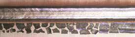
Figure 1: Easy slag removal and beautiful bead appearance
right after welding of [P] DW-308L
The DW-Series stainless steel FCWs provide excellent arc stability with not only 100%CO2 but also Ar-CO2 mixed shielding gases. Furthermore, as [P] DW-308L and [P] DW-316L are designed to offer easy slag removal after welding, the temper color on bead surfaces can be avoided as shown in Figure 1. Preventing the generation of temper color can save time spent on acid treatment and raise productivity.
Besides the DW-Series, KOBE STEEL also offers metal type FCWs, including the MX-Series FCWs; the MM-Series FCWs used for the MX-MIG Process, Metal Inert Gas (MIG) Welding with 100% Ar shielding; TG-X-Series filler rods for TIG root pass welding without purging gas; and the DW-N-Series FCWs for welding Nickel-based alloy.
3.Standards of stainless steel FCWs
The three well known standards related to welding are JIS, AWS and ISO. Their respective classifications are shown in Table 1. FCWs are classified by the chemical composition of the weld metal, type of shielding gas and applicable welding position.
Table 1: Classification by standards
(1) JIS Z 3323-2007
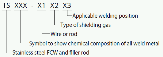
(2) AWS A5.22-2012
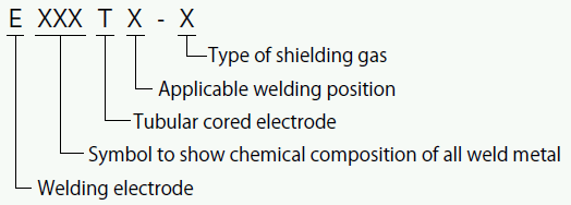
(3) ISO 17633-2017
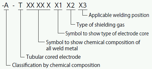
As an example, how [P] DW-308L is classified under each standard is shown in Table 2. Symbols such as 308 or 316, which show the chemical compositions of all weld metal in the trade names of stainless steel FCWs, correspond to JIS and AWS classifications in general.
| Standard | Classification |
|---|---|
| JIS Z 3323-2007 | TS308L-FB0 |
| AWS A5.22 | E308LT0-1 E308LT0-4 |
| ISO 17633 | -A -T 19 9 L R C1 3 -A -T 19 9 L R M21 3 |
4.DW-Series stainless steel FCWs
4-1. DW-Series stainless steel FCWs for general purposes
The DW-Series stainless steel FCWs for general purposes provide excellent usability in flat position welding as well as horizontal fillet welding. The zero (0) in the AWS and JIS classifications indicates the welding position. Typical DW-Series stainless steel FCWs for general purposes are as shown in Table 3.
Users should select a particular FCW by the base metal and intended use, as shown in Table 4.
| Trade name | AWS A5.22 | JIS Z 3323 | Major chemical composition |
Applicable welding position |
|---|---|---|---|---|
| DW-308 | E308T0-1/4 | TS308-FB0 | 20Cr-10Ni | Flat & horizontal fillet |
| [P] DW-309 | E309T0-1/4 | TS309-FB0 | 24Cr-13Ni | Ditto |
| [P] DW-316 | E316T0-1/4 | TS316-FB0 | 19Cr-12Ni-2.3Mo | Ditto |
| [P] DW-347 | E347T0-1/4 | TS347-FB0 | 19Cr-11Ni-0.6Nb | Ditto |
| Stainless steel FCWs | Base metals |
|---|---|
| 308 | 304 |
| 308L | 304L |
| 309 | Dissimilar material |
| 309L | Ditto |
| 316 | 316 |
| 316L | 316L |
| 347 | 321, 347 |
As the crack resistance tends to deteriorate when the ferrite content in the weld metal is low in general, [P] DW-308 and [P] DW-316 are designed to provide about 10% ferrite content in the all weld metal because crack resistance tends to drop when the ferrite content in the weld metal is low.
4-2. Low carbon DW-Series stainless steel FCWs
An L attached to the symbol for chemical composition indicates low carbon type and is suited to weld a similar low carbon base metal. A weld containing high carbon may have reduced tensile strength because the chromium carbide that is generated at the heat affected zone (HAZ) causes the intergranular corrosion resistance to drop. However, a low carbon stainless steel is usually superb in intergranular corrosion resistance. Therefore, attention should be paid. Typical low carbon stainless steel FCWs are shown in Table 5.
| Trade name | AWS A5.22 | JIS Z 3323 | Major chemical composition |
Applicable welding position |
|---|---|---|---|---|
| [P] DW-308L | E308LT0-1/4 | TS308L-FB0 | 20Cr-10Ni | Flat, horizontal fillet |
| [P] DW-309L | E309LT0-1/4 | TS309L-FB0 | 24Cr-13Ni | Ditto |
| [P] DW-316L | E316LT0-1/4 | TS316L-FB0 | 19Cr-12Ni-2.3Mo | Ditto |
4-3. DW-Series stainless steel FCWs for all position welding
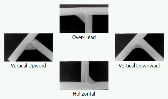
Figure 2: Cross-setion of macrostructure of [P] DW-308LP
fillet weld (304L base plate of 3 mm thick)
An FCW with a suffix [P] in the product name indicates it is for all position (or positional) welding. It provides beautiful bead shape in vertical (upward) and overhead position welding, as shown in Figure 2. In the AWS and JIS classifications, the one (1) indicates the welding position. Typical DW-Series stainless steel FCWs for all position welding are shown in Table 6.
| Trade name | AWS A5.22 | JIS Z 3323 | Major chemical composition |
Applicable welding position |
|---|---|---|---|---|
| [P] DW-308LP | E308LT1-1/4 | TS308L-FB1 | 20Cr-10Ni | All position |
| [P] DW-309LP | E309LT1-1/4 | TS309L-FB1 | 24Cr-13Ni | Ditto |
| [P] DW-316LP | E316LT1-1/4 | TS316L-FB1 | 18Cr-12Ni-2.8Mo | Ditto |
4-4. DW-Series stainless steel FCWs for low temperature service
An LT in the product name indicates the FCW is intended for low temperature service. At low temperatures, toughness generally deteriorates when the ferrite content in the weld metal increases; therefore, this type of FCW is designed to restrain ferrite content. At the same time, it is also designed to maintain the absorbed energy equal to or more than 27J at -196 °C (the boiling temperature of liquified nitrogen). On the other hand, as the hot crack resistance drops when ferrite is low, the balance between toughness and hot crack resistance should be considered when designing; nevertheless, it is necessary to pay full attention to the welding procedures such as excess welding current and speed as well as a wide groove application in order to restrain hot cracks during welding.
Table 7 shows typical DW-Series stainless steel FCWs for low temperature service and their properties.
| Trade name | AWS A5.22 | JIS Z 3323 | Chemical composition of all weld metal (mass%) | Tensile properties | Impact properties (-196°C) | ||||||||
|---|---|---|---|---|---|---|---|---|---|---|---|---|---|
| C | Si | Mn | Ni | Cr | Mo | FN* | TS (MPa) | El (%) | Absorbed energy (J) | Lateral expansion (mm) | |||
| [P] DW-308LT | E308LT0-1/4 | TS308L-FB0 | 0.021 | 0.31 | 2.49 | 10.36 | 18.58 | - | 3 | 530 | 51 | 38 | 0.60 |
| [P] DW-316LT | E316LT1-1/4 | TS316L-FB0 | 0.020 | 0.37 | 1.58 | 11.89 | 17.57 | 2.20 | 5 | 530 | 44 | 39 | 0.56 |
*FN: Ferrite number based on DeLong Diagram.
4-5. DW-H-Series stainless steel FCWs for high temperature service
In many of the DW-Series stainless steel FCWs for general purposes, an extremely small amount of bismuth trioxide (Bi2O3), a low-melting-metal-oxide, is added to improve slag removability.
However, Bismuth (Bi), a surface activating element, segregates at the boundary and can promote breakage under a sustainable tensile load when it is exposed to high temperatures for a long time. Therefore, according to AWS, a stainless steel FCW containing Bi is unsuitable for use in circumstances exceeding 400 °C or for post weld heat treatment (PWHT) exceeding 500 °C.
The DW-H-Series FCWs, which do not contain Bi, have been developed for use in high temperature environments and are suitable for such applications.
Although JIS Z 3323 specifies that the Bi content in the all weld metal be under 10 ppm (0.001%), this amount is practically interpreted as no addition of Bi, in other word, Bi-free. Hence, BiF indicates a Bi-free type of stainless steel welding consumable, such as in YF308C-BIF.
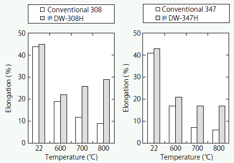
Figure 3: The effect of Bi on ductility at high temperatures
The typical DW-H-Series stainless steel FCWs for high temperature service are shown in Table 8. The effects of Bi on high temperature tensile tests on 308 and 347 type weld metals are shown in Figure 3.
| Trade name | AWS A5.22 | JIS Z 3323 | Chemical composition of all weld metal (mass%) | Tensile properties | |||||||||
|---|---|---|---|---|---|---|---|---|---|---|---|---|---|
| C | Si | Mn | Ni | Cr | Mo | Bi | N | FNW* | TS (MPa) | El (%) | |||
| [P] DW-308H | E308HT1-1/4 | TS308H-BiF-FB0 | 0.056 | 0.49 | 1.16 | 9.14 | 18.65 | - | <0.001 | 0.028 | 5 | 607 | 47 |
| [P] DW-308LH | E308LT1-1/4 | TS308L-BiF-FB0 | 0.026 | 0.41 | 1.35 | 10.20 | 18.70 | - | <0.001 | 0.030 | 4 | 540 | 52 |
| [P] DW-316H | E316T1-1/4 | TS316H-BiF-B0 | 0.059 | 0.52 | 1.16 | 11.48 | 19.03 | 2.32 | <0.001 | 0.026 | 7 | 584 | 45 |
| [P] DW-316LH | E316LT1-1/4 | TS316L-BiF-FB0 | 0.023 | 0.45 | 1.08 | 11.94 | 18.47 | 2.45 | <0.001 | 0.030 | 7 | 540 | 45 |
| [P] DW-347H | E347T1-1/4 | TS347-BiF-FB0 | 0.059 | 0.45 | 1.59 | 9.57 | 18.92 | Nb: 0.69 | <0.001 | 0.034 | 5 | 662 | 34 |
| [P] DW-309LH | E309LT1-1/4 | TS309L-BiF-FB0 | 0.028 | 0.47 | 1.24 | 12.58 | 24.17 | - | <0.001 | 0.021 | 20 | 578 | 39 |
| [P] DW-310 | E310T0-1/4 | TS310-FB0 | 0.18 | 0.42 | 2.01 | 20.73 | 25.76 | - | <0.001 | 0.019 | 0 | 620 | 40 |
*FNW: Ferrite number based on WRC-1992 Diagram.
It is clearly seen that Bi-free weld metal is superior in ductility at high temperature to weld metals containing Bi.
The DW-H-Series stainless steel FCWs are designed to produce lower ferrite than conventional stainless steel FCWs. This is because ferrite in the weld metal transforms to a brittle sigma (σ) phase at high temperature and causes mechanical properties of the weld metal to deteriorate. As a criterion of ferrite content, the API PR582 3rd Edition specifies that 9 FN (based on WRC Diagram-1992) or less shall be maintained if the weld metal is exposed to temperatures exceeding 538 °C.
4-6. Low Cr(VI) emission DW-XR-Series stainless steel FCWs
Welding fumes are a complex mixture of metallic oxides, silicates, and fluorides that come from metal vapor during welding. In the case of welding stainless steel, the fume contains about 5 to 20% chromium (Cr) oxide, a part of which exists as the hazardous 6-valent chromium compound, Cr(VI). Accordingly, strict control of Cr(VI) is now a worldwide trend.
DW-XR-Series stainless steel FCWs are designed to reduce Cr(VI) in the welding fume. 308L, 316L and 309L stainless steel FCWs were targeted for the development of DW-XR-Series stainless steel FCWs for flat and horizontal fillet welding as well as for all position welding. The present line-up is shown in Table 9.
| Trade name | AWS A5.22 | Major chemical composition |
Applicable welding position |
|---|---|---|---|
| DW-308L-XR | E308LT0-1/4 | 20Cr-10Ni | Flat & horizontal fillet |
| [P] DW-309L-XR | E309LT0-1/4 | 24Cr-13Ni | Ditto |
| [P] DW-316L-XR | E316LT0-1/4 | 18Cr-12Ni-2.3Mo | Ditto |
| [P] DW-308LP-XR | E308LT1-1/4 | 20Cr-10Ni | All position |
| [P] DW-309LP-XR | E309LT1-1/4 | 24Cr-13Ni | Ditto |
| [P] DW-316LP-XR | E316LT1-1/4 | 18Cr-12Ni-2.3Mo | Ditto |
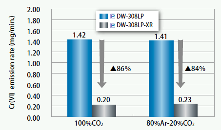
Figure 4: Comparison of Cr(VI) emission rate between
[P] DW-308LP-XR and conventional [P] DW-308LP
Figure 4 compares the Cr(VI) emission rate between [P] DW-308LP-XR and conventional [P] DW-308LP, which was measured according to ISO 15011-1 and ISO 16740.
It shows that the Cr(VI) emission rate of [P] DW-308LP-XR is substantially reduced to 1/6 that of [P] DW-308LP.
4-7. DW-G-Series stainless steel FCWs for sheet metal
DW-G-Series stainless steel FCWs enable stable welding on sheet metals even at low welding current. To be more precise, though the welding of sheet metals requires 0.9 mm diam eter (φ) when a conventional FCW or solid wire is used, with DW-G-Series FCWs, 1.2 mmφ can be used, which is more convenient and less expensive. Table 10 shows the line-up of DW-G-Series stainless steel FCWs.
| Trade name | AWS A5.22 | JIS Z 3323 | Major chemical composition |
Applicable welding position |
|---|---|---|---|---|
| [P] DW-G308L | E308LT0-1/4 | TS308L-FB0 | 20Cr-10Ni | Flat and horizontal fillet |
| [P] DW-G309L | E309LT0-1/4 | TS309L-FB0 | 24Cr-13Ni | Ditto |
| [P] DW-G316L | E316LT0-1/4 | TS316L-FB0 | 19Cr-12Ni-2.3Mo | Ditto |
The relationship between leg length and welding speed in horizontal fillet welding is shown in Figure 5, while Figure 6 shows the optimum range of welding parameters of the DW-G-Series stainless steel FCWs (1.2 mmφ) in comparison with conventional FCWs (0.9 mmφ).
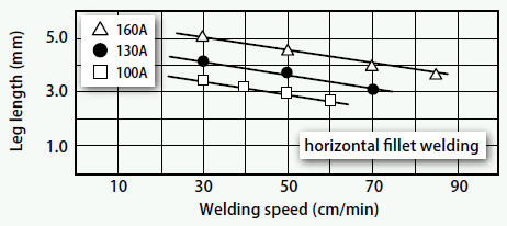
Figure 5: Relationship between leg length and welding
speed in horizontal fillet welding by DW-G-Series
stainless steel FCW (1.2 mmφ)
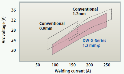
Figure 6: Optimum range of welding parameters
by DW-G-Series
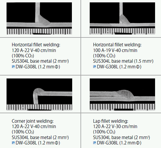
Figure 7: Application of sheet metal welding
by [P] DW-G308L (1.2 mmφ)
Although the DW-G-Series FCWs are available in a size of 1.2 mmφ only, they allow for low current welding of about 100A as well as smaller leg length down to about 3 mm. The welding of sheet metals with plate thickness of 1.0-2.0 mm, which was not easy with conventional FCWs or solid wires, has become possible with 1.2 mmφ DW-G-Series FCWs as shown in Figure 7.
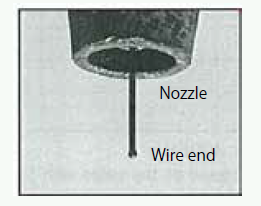
Figure 8: Wire end of DW-G-Series FCW
Additionally, another advantage of DW-G-Series FCWs is that, because they are excellent in arc restarting, clipping off the wire end during intermittent or tack welding is not necessary. The state of wire end is shown in Figure 8.
4-8. DW-N-Series FCWs for Ni-based alloy
The N (Nickel) in the DW-N-Series means nickel base. DW-N-Series FCWs offer usability as excellent as stainless steel FCWs. When DW-N-Series FCWs are utilized in welding operations, it is recommended to avoid excess welding current as well as speed and to make the groove wider as well. Typical DW-N-Series FCWs are shown in Table 11.
| Trade name | AWS A5.34 | JIS Z 3335 | Major chemical composition |
Applicable welding position |
|---|---|---|---|---|
| [P] DW-N625 | ENiCrMo3T1-1/4 | TNi6625-PB1 | 63Ni-21Cr-9Mo-3.5Nb | All position |
| [P] DW-N709SP | ENiMo13T1-1/4 | TNi1013-PB1 | 63Ni-7Cr-18Mo | Ditto |
5.Metal type MX-Series stainless steel FCWs
As the metal type MX-Series stainless steel FCWs have nearly the same deposition efficiency as solid wires, welding operations are more efficient with MX-Series FCWs than with the slag type stainless steel FCWs. Typical MX-Series FCWs are displayed in Table 12.
| Trade name | AWS A5.22 | JIS Z 3323 | Major chemical composition |
Applicable welding position |
|---|---|---|---|---|
| [P] MX-A308L | EC308L | TS308L-MM0 | 20Cr-10Ni | Flat and horizontal fillet |
| [P] MX-A309L | EC309L | TS309L-MM0 | 24Cr-13Ni | Ditto |
| [P] MX-A316L | EC316L | TS316L-MM0 | 19Cr-12Ni-2.3Mo | Ditto |
6.MM-Series stainless steel FCWs for MIG welding with 100% Ar shielding
The MM-Series FCWs are exclusively utilized for the MX-MIG process, which is MIG welding with 100% Ar shielding. The products are available for carbon steel and stainless steel applications.
The MX-MIG process for stainless steel applications has the following features:
(1) The use of pure Ar shielding gas provides the weld metal with the same level of low carbon content as TIG welding.
(2) It can be used in a wider welding current range from as low as about 150 A to as high as about 300 A.
(3) Low spatter and fume generation improves the welding environment.
(4) The low carbon weld metal provides corrosion resistance that is as high as TIG weld metal.
(5) It can create a low dilution rate even at a high welding current range like 300 A that is almost equivalent to CO2 gas shielded arc welding at 150 A.
Typical MM-Series stainless steel FCWs are exhibited in Table 13.
| Trade name | AWS A5.22 | JIS Z 3323 | Major chemical composition |
Applicable welding position |
|---|---|---|---|---|
| [P] MM-308L | E308LT0-G | TS308L-FG0 | 20Cr-10Ni | Flat and horizontal fillet |
| [P] MM-309L | E309LT0-G | TS309L-FG0 | 24Cr-13Ni | Ditto |
| [P] MM-316L | E316LT0-G | TS316L-FG0 | 19Cr-12Ni-2.3Mo | Ditto |
7.TG-X-Series Flux Cored filler rods for TIG root pass welding
For TIG root pass welding on stainless steel pipes, back shielding (or back purging) by 100% Ar gas is normally required in order to prevent oxidation in the back bead. However, the large amount of time and Ar gas required for shielding raises cost enormously.
TG-X-Series Flux Cored filler rods for TIG root pass welding are TIG welding consumables containing flux inside (like conventional FCWs) and do not require back shielding because the slag generated during welding covers the back bead. Another advantage of TG-X filler rods is that no back shielding allows operators to work inside pipes without the danger of asphyxiation.
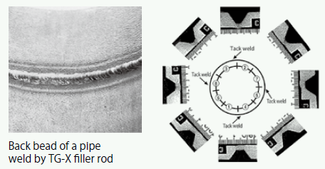
Figure 9: Back bead appearance and macrostructures of
[P] TG-X308L welds by pipe root pass welding
The line-up of TG-X filler rods is shown in Table 14, and back bead appearance and macrostructures of TG-X308L welds by circumferential pipe root pass welding are displayed in Figure 9.
| Trade name | AWS A5.22 | JIS Z 3323 | Major chemical composition |
Applicable welding position |
|---|---|---|---|---|
| [P] TG-X308L | R308LT1-5 | TS308L-RI | 20Cr-10Ni | All position |
| [P] TG-X309L | R309LT1-5 | TS309L-RI | 24Cr-13Ni | Ditto |
| [P] TG-X316L | R316LT1-5 | TS316L-RI | 19Cr-12Ni-2.3Mo | Ditto |
| [P] TG-X347 | R347T1-5 | TS347-RI | 19Cr-10Ni-0.6Nb | Ditto |
The feeding speed by hand of TG-X filler rod is a little different from that of conventional TIG filler rod. In order to steadily melt an optimum quantity of the TG-X filler rod, it should be fed little by little in a fast pitch. Moreover, as it is designed exclusively for root pass welding, using it for the second pass onwards is not recommended because it tends to cause slag inclusion.
8.Schematic diagram of DW-Series stainless steel FCWs
The schematic diagram of DW-Series stainless steel FCWs is shown in Figure 10.
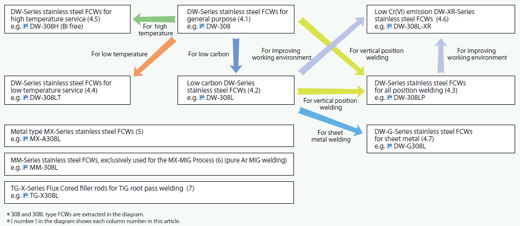
Figure 8: Wire end of DW-G-Series FCW
9.Postscript
KOBE STEEL, LTD. has developed various kinds of stainless steel FCWs as shown in this issue to meet customers’ requirements.
Whenever you face such troubles as how to select or how to use the optimum stainless steel welding consumables, please contact the nearest KOBELCO office(s) or agents.
Reported by
Han Peng,
Reserch Engineer
Welding Process Dept. Technical Center, Welding Business
KOBE STEEL, LTD.
1. KOBELCO WELDING TODAY 2016, Special Edition
2. KOBELCO WELDING TODAY, Vol. 16; No. 3, 2013
3. Research and Development, KOBE STEEL ENGINEERING REPORTS, Vol. 54, No. 2 (April 2004)
Products
- Main Products
- Welding Consumables
- Arc welding robots
- Industries - Recommended Materials
- Welding Handbook Quick View
- Product Quick View & Highlights
- For HEAT-RESISTANT STEEL
- For STAINLESS STEEL
- For LOW-TEMPERATURE STEEL
- Product Highlight
- Catalog
- Technical Highlights
- Certification
- SDS ※English Only
- ARCMAN
- Welding Robot
- Software


