

- Home >
- Education Center >
- The ABC’s of Arc Welding >
- CTOD>
The ABC’s of Arc Welding
CTOD
Welded constructions can rapidly fracture in an unstable manner due to welding defects and fatigue cracks occurring in the stress-concentrated areas of a weldment under lower stresses than expected. Unstable fractures or brittle fractures can occur in unexpectedly short periods of time before the end of the designed service life of the structure. This kind of fracture therefore can cause serious damage of a welded construction.
To prevent unstable fractures, the field of fracture mechanics has been established. Investigations into fracture parameters allow a construction's fracture toughness to be estimated in a systematic manner.
The fracture parameters include stress intensity factor (K), J-integral and Crack Tip Opening Displacement (CTOD). Today, CTOD is most widely employed in structural and component design and in assessment of the acceptability of crack extension and allowable applied loads. CTOD testing has been used mainly for carbon-manganese and low alloy steel in the ductile/brittle transition temperature range, and has found much use in weld procedure tests for work on North Sea offshore structures.
CTOD testing has been specified by British Standard (BS 7448-91), Japan Welding Engineering Standard (WES 1108-95) and American ASTM standard (ASTM El 290-93).
Most CTOD tests consist of three-point bending, using a bend specimen of full-thickness that has a notch and a fatigue pre-crack at the tip of the notch. At the initial stage of loading the specimen, the plastic deformation occurs at the original fatigue crack tip, causing a certain amount of opening displacement at the tip of the crack in the period from R to c―Figure 1.
Introduction of welding consumables for offshore structures
KOBELCO welding consumables for low temperature steel (English only)
The fracture pattern of the specimen is analyzed and identified according to the following descriptions; that is, from completely brittle fracture to fully plastic collapse.
(1) A brittle fracture (either unstable cracking or pop-in in the load-displacement record) occurring at the initial stage of loading; the CTOD value is designated δc.
(2) A brittle fracture occurring following slow (ductile) crack growth; the CTOD value is designated δu.
(3) A slow (ductile) crack growing to fracture the specimen at the maximum load under conditions of stable crack growth; the CTOD value is designated δm.
The CTOD value is determined as the opening displacement (mm) measured with a clip gauge at the tip of the original fatigue crack when the brittle fracture of (1) or (2) above occurs, or when the maximum load has been first attained under the condition of (3). That is, the CTOD value of a particular structure shows the degree to which the structure is durable under applied loads when it contains a crack that can be detected by nondestructive testing. With a larger CTOD value, the structure can accommodate a longer crack or larger loads.
The CTOD value can be affected by temperature and material thickness; thus, the requirement for CTOD is determined according to the service temperature and the maximum wall thickness of the relevant structure; e.g. CTOD at –10°C ≥ 0.25 mm for offshore structures. With the recent trends of ever larger welded constructions and of operating in ever more severe environments at freezing cold seas, the requirements have tended to become stringent.
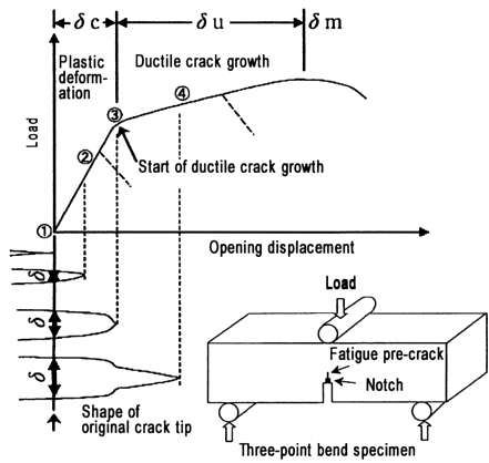
Figure 1. Growth of original fatigue crack and load displacement transition with a three-point bend specimen
(Reference: Kobe Steel's Technical Guide, No. 395, 2003)
Education Center


