

- Home >
- Education Center >
- Welding of Stainless Steel >
- Welding of Stainless Steel >
Welding of Stainless Steel
7. Welding of stainless clad steel
Stainless clad steel comprises the substrate of carbon steel or low alloy steel and the cladded metal of thin (about 2mm thick) stainless steel, which is used for storage tanks and chemical tankers.
Stainless clad steel is based on a concept that corrosion resistance is required only on the surface and that it is less costly than solid stainless steel.
The key point in the welding of clad steel is how to weld the transition zone between the substrate (base metal) and the cladded metal where dissimilar metal welding is required.
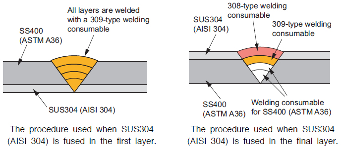
Selection and deposition method in the case of clad steel of SS400 (ASTM A 36) and SUS304 (AISI 304) are shown in the figure below.
When SUS304 (AISI 304) is fused in the first layer weld, a 309−type welding consumable is used in all through the welding groove up to the surface of the joint. When SUS304 (AISI 304) is fused in the final layer, it is necessary to use three different types of welding consumables such that the carbon−steel type for SS400 (ASTM A36), the 309−type for the transition zone, and the 308−type for SUS304 (AISI 304).
Quick guide
KOBELCO WELDING TODAY
8. Key points of welding procedures by various welding processes for stainless steels
(1) General
- ①
- When welding austenitic stainless steels, preheating should be omitted ordinarily and the interpass temperature should be kept at 150℃ or lower.
- ②
- In the case of dissimilar metals welding, refer to Table 7 (Recommended welding consumables for dissimilar metal welding). The weld metal dilution by the base metal (carbon steel and low alloy steel) should also be controlled adequately during welding. When a 309−type welding consumable is used for welding dissimilar metals, it is necessary to use a low welding current because weld cracking may occur if the weld metal dilution by the base metal is excessive.
- ③
- Fully austenitic welding consumables (e.g. NC−30 and DW−310) tend to generate hot cracks and therefore it is necessary to use a low welding current and speed.
(2) Shielded metal arc welding (SMAW)
- ①
- The use of an excessively high current may result in electrode burn, thereby causing poor usability and deteriorated weld metal properties. Therefore, a welding current within the recommended range should be used.
- ②
- The arc length should be kept as short as possible.
- ③
- When weaving is used, its width should be kept up to 2.5 times the electrode diameter.
(3) MAG welding (with flux−cored wires)
- ①
- Power source
A constant voltage DC arc welding power source is suitable with the electrode positive polarity (DCEP). An inverter controlled power source can also be used. With a pulsed power source, spatter emission may increase ; in such a case, the pulse generating circuit should be turned off. - ②
- Shielding gas
100%CO2 gas is suitable for DW stainless steel wires of slag type. Though a mixture of Ar+20~50%CO2 may be used, porosity such as pits and blowholes tend to occur. The flow rate of the shielding gas is to be kept at 20~25liters/min. A mixture of Ar+10~20%CO2 is suitable for MX−A stainless steel wires of metal type. - ③
- Wire extension
The standoff distance of the contact tip from the base metal should be about 15mm for a wire diameter of 0.9mm, and 15~20mm for a wire diameters of 1.2 or 1.6mm. If the wire extension is excessively short, porosity such as pits and elongated blowholes tend to occur. With a mixture of Ar+CO2, the wire extension should slightly be longer than with 100%CO2 gas. - ④
- Measures against wind
When a wind velocity exceeds 1m/sec., the shielding effect for an arc from the wind becomes insufficient and thus porosity tends to occur in the weld metal. Further, N in the atmosphere may be dissolved into the weld metal, thereby deteriorating slag removability or causing hot cracks. Therefore, sufficient quantity of a shielding gas should be flowed and a windbreak screen should be used when it is windy. - ⑤
- Welding fumes
The fume emission rate per unit time in MAG welding is higher than in shielded metal arc welding. Because welding fumes are harmful, either a local fume extraction system or an appropriate respirator should be utilized. - ⑥
- Storage of welding wires
Once DW stainless steel wires have absorbed moisture, they cannot be redried at a high temperature, unlike SMAW covered electrodes. If the welding wire is left in the wire feeder in rainy season or in a highly humid atmosphere in summer or in winter night time when dew condensation can take place, porosity such as pits and elongated blowholes can occur. When storing unpacked welding wires, take care so that dust or dew condensation water may not be attached to the surface of the wire and store it in a dry place where humidity is low.
(4) MIG welding (with solid wires)
- ①
- The welding wire should be used with the DC electrode positive polarity.
- ②
- Ar+2%O2 is used as the shielding gas with a flow rate of 20~25 liters/minute. Ar+10~20%CO2 is not suitable for low carbon stainless steel (e.g. SUS304L) because C will increase in the weld metal.
- ③
- Ordinarily, MIG welding of stainless steel is done in the spray arc welding conditions, in which the arc voltage should be so adjusted that the arc length become 4~6mm. If the arc length is excessively short, blowholes can occur, and, if it is excessively long, the wettability of molten weld metal with the base metal becomes poor.
- ④
- MIG welding is prone to be affected by the wind, causing blowholes in a high wind. Therefore, a windbreak screen should be used when the wind velocity is 0.5m/sec. or higher.
- ⑤
- Pulsed arc welding can produce a stable spray arc in a low current range. Therefore, it is suitable for overlay welding, thin plate welding, and vertical welding.
(5) TIG welding
- ①
- The polarity of the electrode should be DC negative.
- ②
- Ar is ordinarily used as the shielding gas and its appropriate flow rate in manual welding is 7~15liters/minute in the current range of 100~200A. And 12~20liters/minute in the current range of 200~300A.
- ③
- There are two kinds of TIG welding torch. One is with a gas lens and the other is without. Since the gas lens makes the gas flow regular, it brings about a good shielding effect and is especially effective to prevent oxidization of the surface of the weld bead.
- ④
- The appropriate electrode extension from the tip of the welding torch is 4~5mm normally. For welding a corner joint where the shielding effect is poor, it should be 2~3mm. In a deep groove, it should be within 6mm.
- ⑤
- The arc length should be 1~3mm. If it is overly long, the shielding effect becomes poor.
- ⑥
- In melt−through welding, back−shielding is made to prevent oxidization of the back bead. However, with flux−cored filler rods exclusively designed for melt−through welding of stainless steel, a sound back bead can be obtained without back−shielding.
(6) Submerged arc welding
- 1) Joint configuration
- ①
- When performing double−sided welding without back−chipping, welding parameters should be well examined to prevent insufficient penetration and burn−through.
- ②
- When there is a fear of burn−through, shielded metal arc welding should be used for the root pass.
- ③
- On thick plates, normally a double−sided groove configuration should be adopted to prevent welding distortion.
- ④
- In a welding groove, multi−pass−per−layer welding brings about good slag removability.
- 2) Storage and redrying of flux
- ①
- As bonded fluxes are apt to absorb moisture, they should be stored in a dry room.
- ②
- If a boned flux has absorbed moisture, it is necessary to redry at 200~300℃ for about an hour.
- 3) Welding current
- ①
- The use of a high welding current can cause deterioration of the corrosion resistance of the heat−affected zone (HAZ) and the coarsening of the HAZ grain size.
- ②
- A welding current suitable for the wire diameter should be selected.
- ③
- When the wire diameter is small (2.4mm or smaller), DC welding is better as it is easier to control penetration and the shape of the weld bead.
- ④
- As penetration is prone to become deep (thus dilution by the base metal is big), caution is required in the welding of dissimilar metal joint of stainless steel and carbon steel. Especially, double−sided single−run welding should never be adopted for dissimilar metal joints.
- 4) Arc voltage
- ①
- If the arc voltage is overly low, burn−through can occur in the root pass or insufficient fusion can occur on both sides of the weld bead.
- ②
- If arc voltage is too high, sufficient penetration cannot be obtained.
- ③
- As consumption of the flux varies according to the arc voltage, the chemical composition of the weld metal can also fluctuate.
- ④
- Ordinarily, the proper arc voltage is 30~34V.
- 5) Flux distribution depth/height
- If the flux distribution depth/height is excessive, the weld bead surface can be irregular. To prevent this, it is necessary to minimize the flux depth/height so that the arc will not become visible.
Click here for Flux cored TIG rod "TG-X" at Technical Highlight Vol.6
Education Center


